28
CamCor CT and PRO Series Hardware Manual
Section 4
28
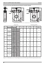
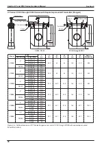
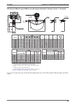
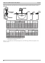
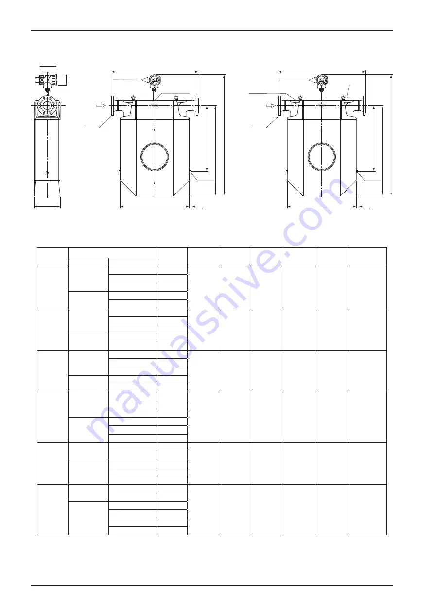
CT Series CC100 through CC250 Sensor with Integral Transmitter (Flanged)
5.28
9.06
2.525.0
2.36
Conduit
connections
3/4-14 FNPT
(M25)
A
H
h1
h2
W
0.59
L
Flow direction
Ground screw
Flange
Boss
1/4-18 FNPT
Conduit
connections
3/4-14 FNPT
(M25)
H
h1
h2
W
0.59
L
Flow direction
Ground screw
Ground screw
Flange
Conduit connections are 3/4-14 FNPT for CSA units and M25 for ATEX units.
Boss
1/4-18 FNPT
CC100, CC150
CC15H through CC250
Model
Flange
L
(in.)
H
(in.)
h1
(in.)
h2
(in.)
A
(in.)
W
(in.)
Approx.
Weight (lb)
Nominal size Flange rating
CC100
4"
ASME 150
40.1
55.2
40
26
11.8
31.9
509
ASME 300
40.8
ASME 600
42.6
DN100
PN 10, 16
38.1
PN 25, 40
39.1
CC150
6"
ASME 150
51.9
55.2
40
26
11.8
31.9
542
ASME 300
52.7
ASME 600
54.6
DN150
PN 10, 16
49.2
PN 25, 40
50.8
CC15H
6"
ASME 150
42.8
63.1
46.9
33.5
12.6
31.9
683
ASME 300
43.6
ASME 600
45.6
DN150
PN 10, 16
40.1
PN 25, 40
41.7
CC200
8"
ASME 150
55.8
63.1
46.9
33.5
12.6
31.9
750
ASME 300
56.6
ASME 600
58.8
DN200
PN 10, 16
52.7
PN 25
54.1
PN 40
54.7
CC20H
8"
ASME 150
55.8
72
54.7
37.8
16.5
43.7
1345
ASME 300
56.6
DN200
PN 10, 16
52.7
PN 25
54.1
PN 40
54.7
CC250
10"
ASME 150
69.8
72
54.7
37.5
16.5
43.7
1433
ASME 300
71.1
DN250
PN 10
67.1
PN 16
67.3
PN 25
68.7
PN 40
70
Figure 4.6—Outline dimensions of CT Series flanged sensor units CC100 through CC250 with integral transmitter (inches)
Summary of Contents for CamCor CC001
Page 14: ...14 CamCor CT and PRO Series Hardware Manual Section 3 This page is left blank intentionally ...
Page 24: ...24 CamCor CT and PRO Series Hardware Manual Section 3 This page is left blank intentionally ...
Page 54: ...54 CamCor CT and PRO Series Hardware Manual Section 5 This page is left blank intentionally ...
Page 62: ...62 CamCor CT and PRO Series Hardware Manual Section 7 This page is left blank intentionally ...


