CamCor CT and PRO Series Hardware Manual
39
Section 5
Section 5—Installation
INSTALLATION GUIDELINES
•
Select a location easy to access for inspection and maintenance.
•
Avoid a location subject to
–
excessive temperature variation and vibration
–
direct exposure to the sun (Provide a sunshade or similar protection to keep the meter out of exposure to direct
sunlight if necessary.)
– immersion in water
–
corrosive gases
– dust and mist
•
Keep the device at least one meter away from sources of electromagnetic induction, such as large transformers and
motors.
•
To ensure consistent and accurate measurement, adhere to all instructions in this section of the manual.
•
Install where pipeline oscillation is held below 0.3G to ensure consistent and accurate measurement. External vibration
(including pulsation), particularly with the same frequency as the drive frequency of the measuring pipe, may affect the
measurement. Contact Cameron regarding the drive frequency of each model.
•
Locate the control valve downstream of the flow meter. Where cavitation is likely to occur, install the flow meter at
least five meters away.
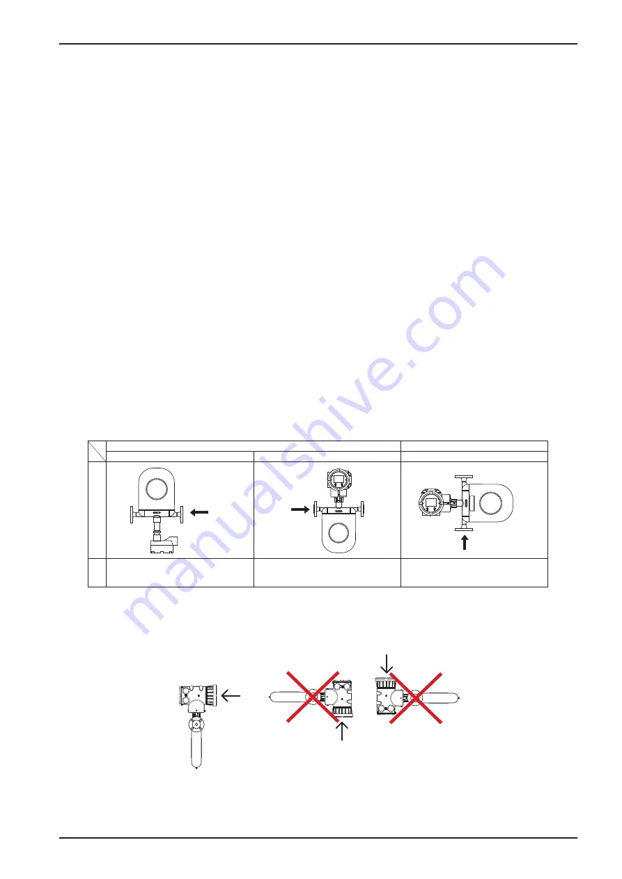
CT SERIES METER PHYSICAL ORIENTATION
The sensor may be installed either in a horizontal run or vertical run. The following physical orientations are suggested,
depending on the type of process fluid. For example,
, No. 2 shows the typical orientation for liquids. If the con
-
duit connection points up, make provisions for sealing off or keeping rainwater and other moisture from entering the meter.
Physical orientation must be specified at the time of order.
CT Series CC003 through CC250 Meters
Horizontal run
Vertical run
No.1
No.2
No.3
●
Gases
●
Slurries
●
Liquids
●
Slurries (requiring cleaning)
●
Liquids
●
Gases
1. For installation orientation in No. 1, Cameron recommends the separately-mounted transmitter. If the integral transmitter is preferred, contact
Cameron.
2. The measuring tube of the CC003 is in double-loop configuration without self-draining feature.
Orientation
Fluids
Flow
direction
Flow
direction
Flow
direction
Figure 5.1—Physical orientation examples for horizontal and vertical runs
Side view
Bottom view
Top view
Figure 5.2—Transmitter orientation is correct if its display face is not in the horizontal plane.
For the orientation a of separately-mounted transmitter, see
Installing the Separately-mounted Transmitter, page
.
Summary of Contents for CamCor CC001
Page 14: ...14 CamCor CT and PRO Series Hardware Manual Section 3 This page is left blank intentionally ...
Page 24: ...24 CamCor CT and PRO Series Hardware Manual Section 3 This page is left blank intentionally ...
Page 54: ...54 CamCor CT and PRO Series Hardware Manual Section 5 This page is left blank intentionally ...
Page 62: ...62 CamCor CT and PRO Series Hardware Manual Section 7 This page is left blank intentionally ...


