44
CamCor CT and PRO Series Hardware Manual
Section 5
INSTALLATION
Flange Meters
•
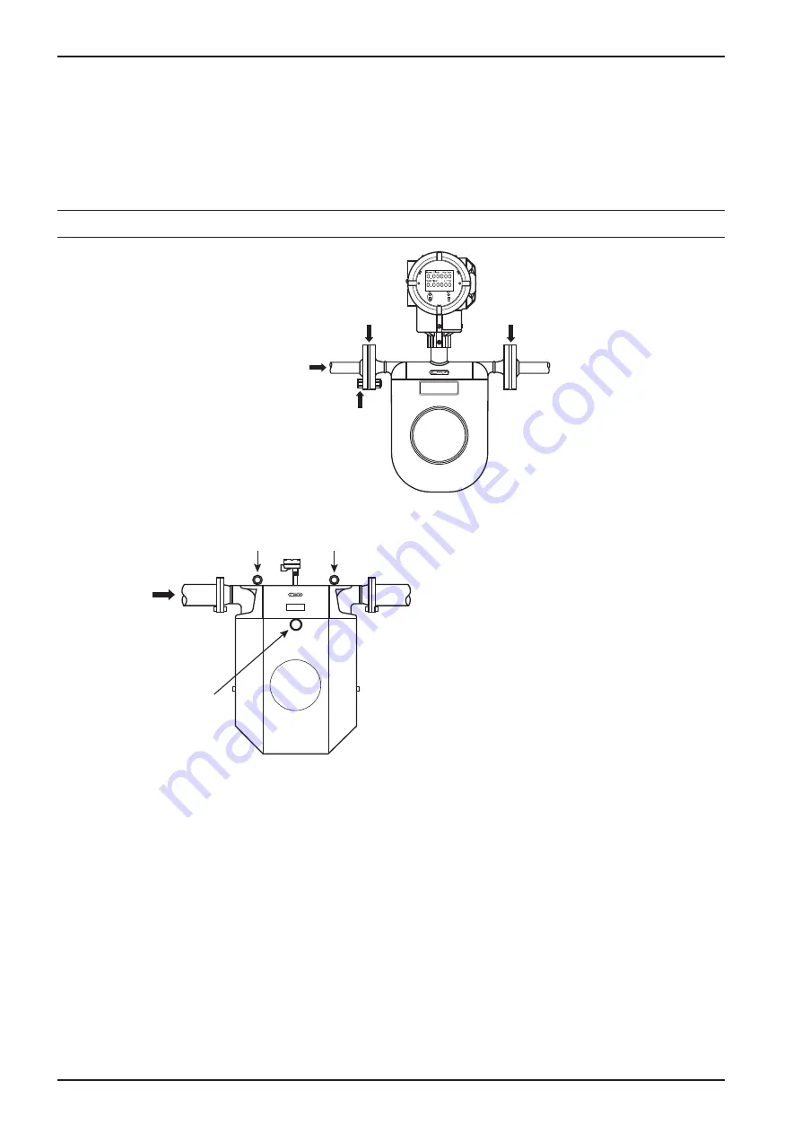
In order to avoid strains on sensor flanges, be sure to correct the flange face-to-face dimension, tilt and concentric
alignment of pipes immediately before and after the sensor.
•
Ensure the flow direction in the pipe matches the direction of the arrow on the front of the flow direction plate.
•
Align the sensor flange O.D. with the flange O.D. of the pipeline, install gaskets, and tighten hex bolts evenly.
CAUTION
Remove the factory-installed protective seals on the sensor flanges before installing the meter.
Flow direction
Hex bolt
Gasket
Gasket
Figure 5.9—Flange meter
Flow direction
Center of gravity
CAUTION
Because of the potential risk to personnel and equipment
due to the weight of Models CC150 through CC250
(500 lb or greater), we recommend that installation be
performed only by qualified personnel experienced in
sling work and crane operation. Note that center of
gravity is shown to facilitate installation in a vertical run.
The eyebolts shown in this diagram may be removed
after installation in the piping assembly. If the eyebolts
are retained, they should be tightened periodically to
counteract loosening caused by vibration.
Eyebolt
Eyebolt
Figure 5.10—Location of the meter’s center of gravity
Sanitary Fittings
The sanitary fitting uses clamp connections and G3447 stainless steel sanitary tubes as piping material. Install according to
the procedure below.
1. Weld the companion sleeves furnished to the piping. Pay attention to the perpendicularity of the ferrule end face and
the difference in height at the weld.
2. Insert the gasket between the sensor and ferrule, aligning it with the groove in the ferrule-end face, and tighten with the
clamp.
Summary of Contents for CamCor CC001
Page 14: ...14 CamCor CT and PRO Series Hardware Manual Section 3 This page is left blank intentionally ...
Page 24: ...24 CamCor CT and PRO Series Hardware Manual Section 3 This page is left blank intentionally ...
Page 54: ...54 CamCor CT and PRO Series Hardware Manual Section 5 This page is left blank intentionally ...
Page 62: ...62 CamCor CT and PRO Series Hardware Manual Section 7 This page is left blank intentionally ...

