52
CamCor CT and PRO Series Hardware Manual
Section 5
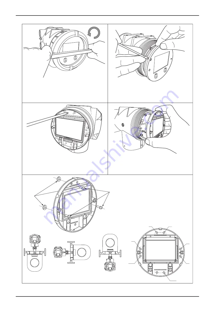
Using a flat tool approximately 10-mm wide, loosen
the transmitter lid by turning it counterclockwise,
being careful not to damage the finish. Remove the
loosened lid by hand.
Using a flathead screwdriver, disengage all three
hooks holding the faceplate in place.
Loosen the three fitting screws holding the display
assembly in place (see Figure 5 for locations). Do
not remove screws; set washers on the back of the
display will prevent the screws from falling out.
Remove the fitting screws and washers
as shown in the diagram to the left,
adjust the LCD display to the desired
orientation, and replace the fitting
screws and washers in the appropriate
holes using the diagrams below.
Remove the display assembly.
Set
washers
(3)
M2.6 LCD
fitting screws
(3)
A
B
C
A,B
B,C
A
C
A
Liquid service,
horizontal run
B
Vertical run
C
Gas service,
vertical run
Figure 5.24—Procedure for changing the transmitter display orientation (Part 1 of 2)
Summary of Contents for CamCor CC001
Page 14: ...14 CamCor CT and PRO Series Hardware Manual Section 3 This page is left blank intentionally ...
Page 24: ...24 CamCor CT and PRO Series Hardware Manual Section 3 This page is left blank intentionally ...
Page 54: ...54 CamCor CT and PRO Series Hardware Manual Section 5 This page is left blank intentionally ...
Page 62: ...62 CamCor CT and PRO Series Hardware Manual Section 7 This page is left blank intentionally ...


