66
CamCor CT and PRO Series Hardware Manual
Section 8
M O D E
S E L E C T
Mass Flow
Vol Flow
lb/min
gal/min
To t a l i z e r 1
To t a l i z e r 2
oz
oz
A n a . O u t p u t 1
A n a . O u t p u t 2
%
%
T x r s t a t u s
A n a . 1 O u t S a t u r a
S c a l e O v e r
Click ENT
(with
↓
)
Click ENT
(with
↓
)
Click ENT
(with
↓
)
Click ENT
(with
↓
)
Click ENT
(with
↓
)
Click ENT
(with
↓
)
Click ENT
(with
↓
)
Click ENT
(with
↓
)
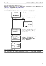
See “SEL Operation” in the “Switch Operation” section of the manual for information about
changing the scroll arrow direction (lower left of the screen).
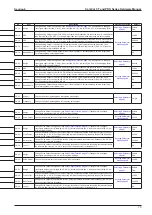
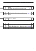
Ana. Output 1:
% Analog Output 1. Measurement range is
–10% to 110%.
Ana. Output 2:
% Analog Output 2. Measurement range is
–10% to 110%.
Txr Status:
Status/error information. This screen does not
appear unless there is status or error information. For
details, see the “Status Messages” and/or “Error
Messages” section of this manual.
Mode Select
screen:
Enter the Setup screen from this
screen. Parameter configuration and various functions can
be accessed from this screen.
Touching the ENT switch from the
Mode Select
screen
returns you to the initial screen.
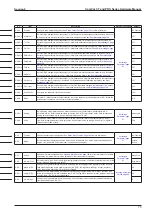
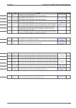
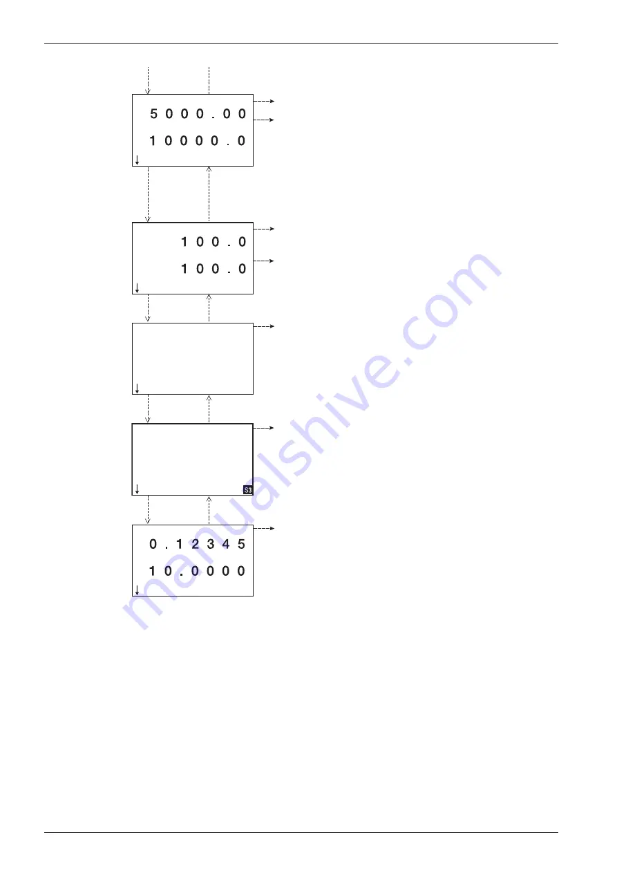
Totalizer1:
Total flow of Pulse Output 1.
Totalizer2:
Total flow of Pulse Output 2. When a Pulse
Ouput 2-related parameter is changed, the counter resets
to zero.
For both, the counter resets to zero with the next count
after the reading exceeds the maximum value. Decimal
point placement can be configured (see Transition Chart 1,
No 1-3-4-4 and 1-3-4-5). The reading is retained regardless
of power cycling. The readings can be manually reset to
zero using the Count/Total reset function (see Transition
Chart 6, No. 3-5-1 and 3-5-2).
Figure 8.6—Variable screens
(
)
Changing the Variable View
.
Additionally, the display font size can be changed. In the default setting (shown in
),
two variables appear on one screen. Selecting the standard font enables three items to be displayed on one screen. For de
-
Summary of Contents for CamCor CC001
Page 14: ...14 CamCor CT and PRO Series Hardware Manual Section 3 This page is left blank intentionally ...
Page 24: ...24 CamCor CT and PRO Series Hardware Manual Section 3 This page is left blank intentionally ...
Page 54: ...54 CamCor CT and PRO Series Hardware Manual Section 5 This page is left blank intentionally ...
Page 62: ...62 CamCor CT and PRO Series Hardware Manual Section 7 This page is left blank intentionally ...


