70
CamCor CT and PRO Series Hardware Manual
Section 8
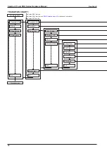
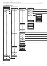
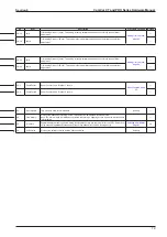
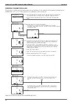
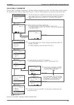
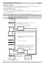
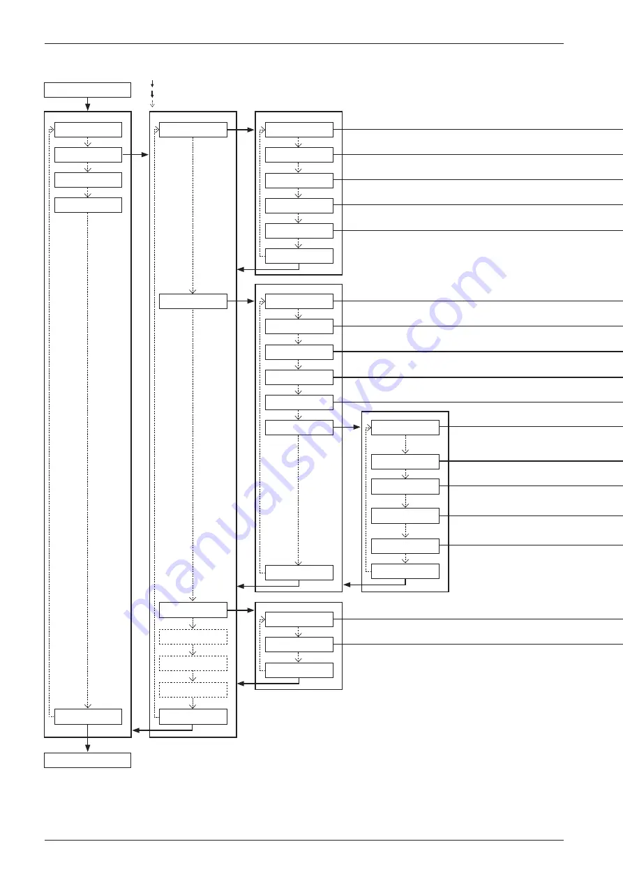
TRANSITION CHART 2
MODE SELECT
Process screen
1.Password & Disp
2.Setup
1.Flow Param
2.Dens Param
1.Mass Unit
2.Vol Unit
3.Flow Damp
4.Flow Cutoff
1.Dens Compen
2.Std Temp
Exit
Exit
3.Diag/Service
4.Maintenance
6.H/L Alarm
3.Exp Coef
4.Settled Dens
5.Dens Value
Exit
5.Flow Direct
Exit
1.Dens Unit
2.Dens Damp
3.Slug Low
4.Slug High
5.Slug Duration
Exit
6.Special Dens
1.Temp Unit
2.Temp Damp
Exit
5.Status Input
4.Outputs
3.Temp Param
indicates SEL1 function
indicates SEL3 function (see
for additional information)
indicates ENT function
Summary of Contents for CamCor CC001
Page 14: ...14 CamCor CT and PRO Series Hardware Manual Section 3 This page is left blank intentionally ...
Page 24: ...24 CamCor CT and PRO Series Hardware Manual Section 3 This page is left blank intentionally ...
Page 54: ...54 CamCor CT and PRO Series Hardware Manual Section 5 This page is left blank intentionally ...
Page 62: ...62 CamCor CT and PRO Series Hardware Manual Section 7 This page is left blank intentionally ...


