CamCor CT and PRO Series Hardware Manual
77
Section 8
No.
Item
Description
Procedure Location
Default
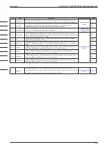
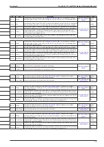
3-1-1-1
Hardware
Run a probe check to identify potential issues.
CAUTION: Under certain circumstances, this check may stop outputs.
—
3-1-1-2
Drive Coil Check
Run a check for an “open” in the drive coil.
CAUTION: Under certain circumstances, this check may stop outputs.
—
3-1-1-3
Txr Condition
Run a check for potential transmitter issues.
—
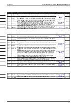
3-1-1-4-1 Back Light
Test the backlight for potential issues (LCD will remain blank during testing). The performance test lasts 18
seconds, cycles through White Background Lit (3 sec), Orange Background lit (3 sec) and Backlight unlit
(3 sec) twice and automatically terminates. Normal LCD illumination is restored upon test completion.
—
3-1-1-4-2 LED
Test LED for potential issues (LCD will remain blank during testing). The performance test lasts 18
seconds alternates 6 times between red LED lit (1.5 sec) and green LED lit (1.5 sec). Normal LCD
illumination is restored upon test completion.
—
3-1-1-4-3 LCD
Test LCD for possible issues by turning all LCD dots off and on. During the test, the LCDs are switched
in and out. The performance test lasts 12 seconds and twice alternates between all dots lit (3 sec) and all
dots unlit (3 sec). Normal LCD illumination is restored upon test completion.
—
3-1-2-1
Static
Run a stability check on the sensor signal at zero flow.
—
3-1-2-2
Dynamic
Run a stability check on the sensor signal while fluid is flowing.
—
3-2-1
Fix Analog1
Produces a simulated output of Analog Output 1 to test cable fault and associated equipment performance.
—
3-2-2
Fix Analog2
Produces a simulated output of Analog Output 2 to test cable fault and associated equipment performance.
—
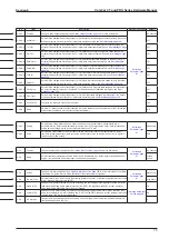
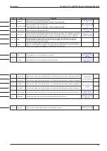
3-2-3
Fix Pulse1
Produces a simulated output of Pulse Output 1 to test cable fault and associated equipment performance.
—
3-2-4
Fix Pulse2
Produces a simulated output of Pulse Output 2 to test cable fault and associated equipment performance.
—
3-2-5
Status Output
Produces a simulated output of Status Output to test cable fault and associated equipment performance.
—
3-2-6
Status Input
Monitor status input to test cable fault and associated equipment performance.
—
3-3-1
Auto Zero
Zeros the meter readings. Before zeroing, ensure that flow is at zero.
—
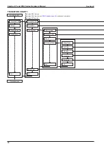
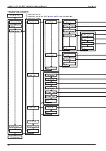
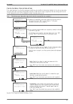
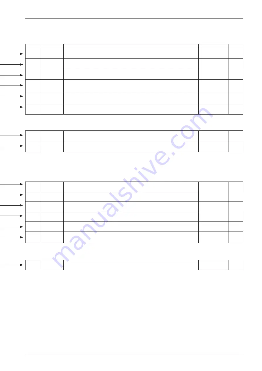
TRANSITION CHART 5
MODE SELECT
Process screen
1.Password & Disp
2.Setup
1.Test/Status
1.Self-Diag
2.Installation
1.Hardware
2.Drive coil Check
1.Back Light
2.LED
3.LCD
Exit
Exit
Exit
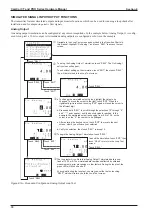
1.Fix Analog1
2.Fix Analog2
Exit
1.Auto Zero
Exit
Exit
4.Maintenance
2.Loop Test
3.Calibration
Exit
3.Txr Condition
4.LCD Test
1.Static
2.Dynamic
Exit
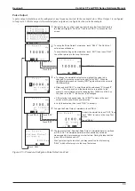
3.Fix Pulse1
4.Fix Pulse2
5.Status Output
6.Status Input
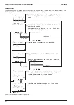
4.Trim Analog
5.Cnt/Ttl Reset
3.Diag/Service
Summary of Contents for CamCor CC001
Page 14: ...14 CamCor CT and PRO Series Hardware Manual Section 3 This page is left blank intentionally ...
Page 24: ...24 CamCor CT and PRO Series Hardware Manual Section 3 This page is left blank intentionally ...
Page 54: ...54 CamCor CT and PRO Series Hardware Manual Section 5 This page is left blank intentionally ...
Page 62: ...62 CamCor CT and PRO Series Hardware Manual Section 7 This page is left blank intentionally ...


