CamCor CT and PRO Series Hardware Manual
87
Section 8
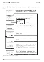
Pipeline Oscillation Check (at Normal Flow)
This check diagnoses your flow measurement installation at normal flow to determine whether it is free from external dis
-
turbances and noises resulting from pipeline vibration or other factors. Upon completion of the check, diagnostic results
will be indicated and you will be prompted to follow the instructions given.
Note
During the process of diagnosis, analog output and pulse output operations are suspended.
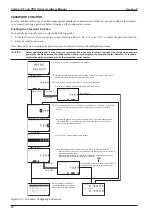
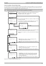
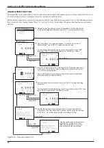
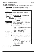
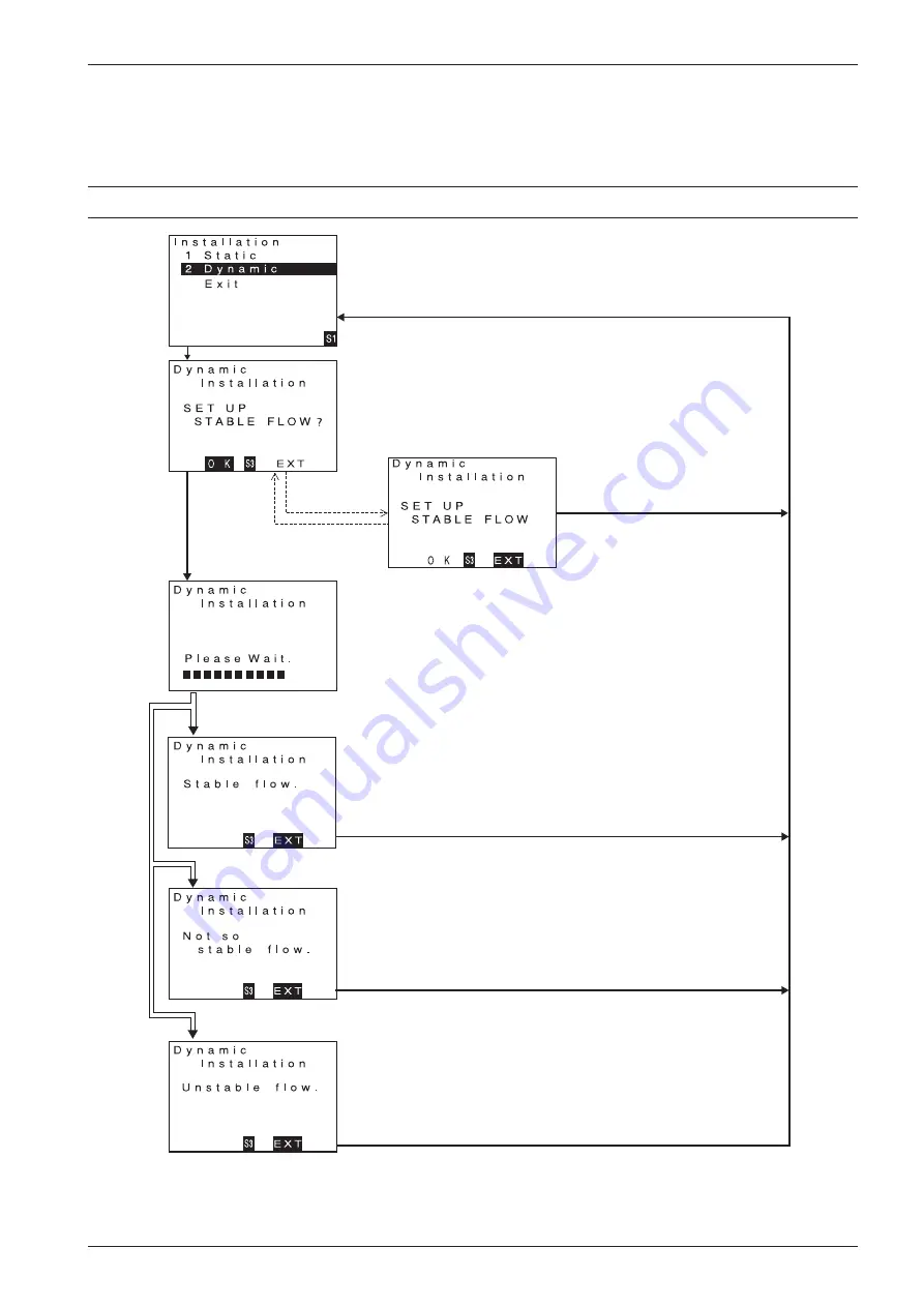
Navigate to the
Installation
screen as described in the Transition Charts in
this manual, then touch “SEL1” to select “Dynamic”. The
Dynamic
Installation
check start screen will appear.
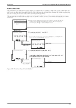
To run a pipeline vibration/oscillation check (dynamic), stabilize the flow and
touch “SEL3” to proceed.
To exit without running a pipeline vibration/oscillation check, touch “ENT,”
then touch “SEL3.” You will be returned to the
Installation
screen.
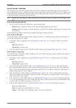
The
Dynamic Installation
screen will appear. The check lasts approximately
30 seconds, during which the green LED will blink on and off.
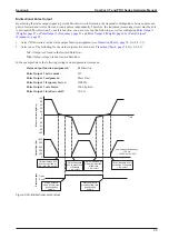
When the check is complete, one of three possible results will be displayed
onscreen:
•
Stable Flow.
Flow conditions are stable and satisfactory for flow
measurement. Use the meter in this state.
Touch “SEL3” to exit the vibration check and return to the
Installation
screen.
•
Not So Stable Flow.
Flow signal fluctuates. To stabilize flow signal
fluctuation, increase the damping factor.
Touch “SEL3” to exit the vibration check and return to the
Installation
screen.
•
Unstable Flow.
In this condition, flow signal fluctuates excessively.
Inspect the pipeline at zero flow using the Pipeline Vibration Check
procedure described in this manual. To stabilize signal fluctuation,
increase the damping factor.
Touch “SEL3” to exit the vibration check and return to the
Installation
screen.
Touch “SEL1.”
Touch “SEL3.”
Touch “ENT.”
Touch “ENT.”
Touch “SEL3.”
Figure 8.15—Procedure: Pipeline Oscillation Check
Summary of Contents for CamCor CC001
Page 14: ...14 CamCor CT and PRO Series Hardware Manual Section 3 This page is left blank intentionally ...
Page 24: ...24 CamCor CT and PRO Series Hardware Manual Section 3 This page is left blank intentionally ...
Page 54: ...54 CamCor CT and PRO Series Hardware Manual Section 5 This page is left blank intentionally ...
Page 62: ...62 CamCor CT and PRO Series Hardware Manual Section 7 This page is left blank intentionally ...

