CamCor CT and PRO Series Hardware Manual
97
Section 8
PULSE OUTPUT FUNCTION
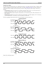
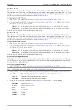
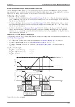
The transmitter is provided with two pulse outputs which can be configured as independent outputs. Features include two
pulse output operating modes, a double-pulse output created by allowing two pulses out of phase by 90 or 180 degrees, and
a bidirectional pulse output linked with status output signal, enabling the operator to determine the direction of flow. Refer
to the following topics for description of these features.
Note
When the pulse output assignment, weight, full-scale flow rate, or frequency at full scale is modified, the Counter/Totalizer will be
reset.
Pulse Output Operating Modes
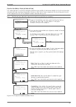
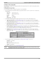
1. Select from the following two available pulse output operating modes:
–
Weight:
Pulses are output according to the number of configured pulses per unit of flow
–
Frequency:
Pulses are output at a specific frequency according to the configured frequency factor, rate factor, and
low cutoff rate.
After selecting the operating mode, follow the operating-mode specific instructions below.
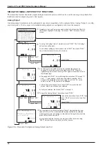
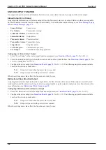
Pulse Output 1 (Weight)
To use Pulse Output 1 in Weight (Scaling) Mode, configure as follows. For bidirectional pulse output or double-pulse out
-
put, configure the parameters as follows.
1.
Set the Pulse Output 1 assignment (see
, No. 2-4-3-1) and select the flow type from the
following:
–
Mass Flow:
Mass flow
–
Volume Flow:
Volumetric flow
2. Select the weight (scaling) factor (0 to 999999) for Pulse Output 1 (see
, No. 2-4-3-2).
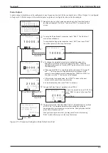
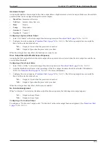
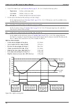
Pulse Output 1 (Frequency)
To use Pulse Output 1 in Frequency Mode, configure as follows. For bidirectional pulse output or double-pulse output, con
-
figure the parameters as follows.
1.
Set the Pulse Output 1 assignment (see
, No. 2-4-3-1) and select the flow type from the
following:
–
Mass Flow:
Mass flow
–
Volume Flow:
Volumetric flow
2. Select the frequency factor of Pulse Output 1 (see
, No. 2-4-3-2). This is the maximum
pulse frequency output by the device under normal operating conditions, generated when the flow rate configured in
Step 3 is measured, and should match the measurable range of the device detecting the transmitter’s pulse output. Ac
-
ceptable setting range is 0.1 Hz to 10000 Hz.
3.
Select the rate factor of Pulse Output 1 (see
, No. 2-4-3-3), which determines the maxi
-
mum flow rate under normal operating conditions. An output at the frequency established in Step 2 will be generated
when the preset flow rate is reached.
4. Select the low-flow cutoff of Pulse Output 1 (see
The output will clamped
at “0” when the proportion of flow rate is smaller than the low-flow cutoff value when the flow rate established in Step
2 reaches 100%. Acceptable setting range is 0.0% to 10.0%.
5.
Select the pulse output error state (see
, No. 2-4-6-2) from the following options:
–
Zero:
Pulse output is halted.
–
Hold:
Last good pulse output before the error is kept.
–
Upscale:
11 kHz output (see
for more information)
Summary of Contents for CamCor CC001
Page 14: ...14 CamCor CT and PRO Series Hardware Manual Section 3 This page is left blank intentionally ...
Page 24: ...24 CamCor CT and PRO Series Hardware Manual Section 3 This page is left blank intentionally ...
Page 54: ...54 CamCor CT and PRO Series Hardware Manual Section 5 This page is left blank intentionally ...
Page 62: ...62 CamCor CT and PRO Series Hardware Manual Section 7 This page is left blank intentionally ...

