CamCor CT and PRO Series Hardware Manual
109
Section 9
Section 9—Maintenance
If an error occurs, an error message will appear at the bottom of LCD display. The sections below will help to identify the
cause of the error and to troubleshoot the issue. If the problem persists, or if you have any question, contact Cameron.
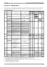
ERROR MESSAGES
Error
Type
Status Message
Description
Action
Error Indicators
Error Output
Red
LED
Green
LED
Back-
light
Ana.
Out 1
Ana.
Out 2
Pulse
Out 1
Pulse
Out 2
Status
Out
Saturated
Alarm
Ana. Out 1 Satur
Analog Output 1-2 out of range (−10% to
110%); failure to produce proper output
Adjust measurement to fall within lower
limit to upper limit of analog output or
modify setting.
Blink
On
Off
21.6 mA
—
—
Per
status
select
AO2
Range
Error
—
Ana. Out 2 Satur
—
21.6 mA
PO2
Range
Error
2.4 mA
Pls. Out 1 Satur
Pulse Output 1-2 exceeds 11kHz; instant
flow rate selected exceeds full-scale flow
rate of pulse output; failure to produce
proper output
Lower instant flow rate or increase full-
scale flow rate.
—
11 KHz
—
Pls. Out 2 Satur
—
11 KHz
Sensor
Failure
Drive Out Of Range
Drive frequency out of normal range;
possible fault in drive coil connections;
failure to make proper measurement
Run self-diagnostics on drive coil
On
Off
Orange
Per error output
setting
Per error output
setting
Per
status
select
Scale Over
Mass flow rate exceeds 110% of maximum
allowable range; possible failure to make
proper measurement
Use within the maximum allowable
range.
Temp Out Of Range
Temperature out of normal range; fault in
temperature sensor; failure to make proper
measurement
Run self-diagnostics on temperature
Density Outside
Density out of normal range (0 to 5 g/mL);
bubble entrapment possible; failure to make
proper measurement
Check for bubble entrapment.
P.O. Sig Err
Pickoff signal voltage out of normal range;
possible fault in pickoff sensor; failure to
make proper measurement
Run self-diagnostics on pickoff coil
Temp Connect Err
Possible fault in temperature sensor wiring
connections
Check temperature sensor connections.
P.O. Connect Err
Possible fault in pickoff sensor wiring
connections
Check pickoff coil connections.
Drive Coil Error
Possible fault in drive coil wiring
connections
Check drive coil connections; run self-
diagnostics on drive coil connections;
.
Transmitter
Failure
EEPROM Err
Error in parameters; inactive operation
Contact Cameron.
Blink
Off
Orange
2.4 mA
Stopped
Off
Data Update Err
Fault in internal data or transmitter
Contact Cameron.
On
Off
Orange
Per error
output
setting
Per error output
setting
Per
status
select
Parameter
Alarm
Ana. 1 Set Alm.
Parameter setting of Analog Output 1-2
in one of the following conditions:
▪ Upper limit < lower limit
▪ Upper or lower limit > maximum
acceptable setting
▪ Upper or lower limit < maximum
acceptable setting
Verify parameters and reconfigure to
acceptable values.
Blink
On
Off
Per error output
setting
Per error output
setting
Per
status
select
Ana. 2 Set Alm.
H/L Po.Set Alm.
H/L alarm parameter setting comes under
any of the following conditions
▪ High alarm < Low alarm
▪ High alarm or low alarm > maximum
acceptable setting
▪ High alarm or low alarm < maximum
acceptable setting
Verify parameters and reconfigure to
.
Calibration
Failure
Auto Zero Fail
Auto zero offset is out of normal range.
Allow fluid flow to return to a steady
state and retry zeroing; see
.
Blink
Off
Off
—
—
Per
status
select
Slug Flow
Alarm
Slug Flow
Alarm remain active for a preset duration
(slug flow check) upon detection of gas
entrapment
Air entrapment in the fluid is a possibility.
Verify the fluid and line for conditions.
Blink
On
Off
Only flow output
clamped
Clamped
Per
status
select
After expiration of slug flow alarm, check
slug flow duration
Flow output
clamped at "0"
Stopped
Transmitter
Alarm
Txr Temp Alm.
Transmitter’s internal temperature is above
80°C
Lower ambient temperature to prevent
shortening of component life.
Blink
On
Off
Continued
Continued
Per
status
select
Switch Alm.
Possible faulty operating switches
Contact Cameron.
Blink
On
Off
Continued
Continued
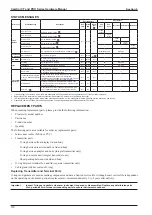
1. If the backlight is set to sleep mode, the white backlight will still illuminate after switch operation even if the operation is stopped.
2. During a parameter error alarm, the LED blinks faster (intervals of 100 ms) than is normal for other alarms (intervals of 250 ms).
3. Transmitter outputs may become erratic in the event of transmitter failure.
4. The orange backlight remains on for 5 minutes after an alarm, or for the sleep duration of the backlight. After this time, the orange backlight will blink on and off.
5. See
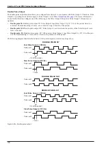
Pulse Output Function, page 97
6. See
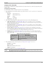
Analog Output Function, page 101
for more information.
7. See
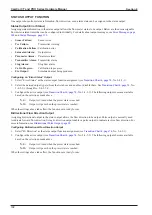
Status Output Function, page 102
for more information.
Summary of Contents for CamCor CC001
Page 14: ...14 CamCor CT and PRO Series Hardware Manual Section 3 This page is left blank intentionally ...
Page 24: ...24 CamCor CT and PRO Series Hardware Manual Section 3 This page is left blank intentionally ...
Page 54: ...54 CamCor CT and PRO Series Hardware Manual Section 5 This page is left blank intentionally ...
Page 62: ...62 CamCor CT and PRO Series Hardware Manual Section 7 This page is left blank intentionally ...

