116
CamCor CT and PRO Series Hardware Manual
Section 10
116
Cable Glands
Use only cable glands that conform to the following requirements:
•
Explosion-proof code: Exd CU
•
Protection class:
IP66 min.
•
Nominal size:
3/4-14 FNPT for CSA units; M25 for ATEX units
Insulation Performance
The following part of the transmitter is subject to insulation:
•
IS circuit terminals (separate detector board: TB20, TB21) - Enclosure
Withstand voltage condition: 500VAC, leak current: 3 to 5mA
Due to the built-in noise eliminator between the transmitter power source terminals (TB1’s L and N) and output terminals
(TB2, TB3 and TB4), and the enclosure respectively, complete insulation is not provided. Withstand voltage tests should be
conducted at voltages of AC 200V or DC 250V and leak current of 3 to 5 mA.
Earth Ground Terminal
1. Using green or green/yellow 10 AWG wire, ground the device at the power source’s GND terminal block or any of the
external grounding terminals. A minimum of D-class grounding is recommended.
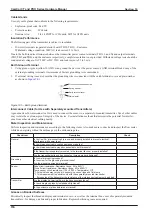
2. If external wiring is used, ensure that the grounding wire is connected with the earth terminal cover and plain washer
as shown in
Cross-recess panhead screw
Spring washer
Earth terminal cover
Plain washer
Figure 10.1—Earth ground terminal
Interconnect Cable (for Use with Separately-mounted Transmitters)
A genuine CamCor interconnect cable is used to connect the sensor to a separately-mounted transmitter. Use of other cables
may violate the explosion-proof integrity of the device. Use installation methods that minimize the potential for interfer
-
ence from other electrical cabling nearby.
Meter Inspection and Maintenance
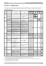
Perform inspection and maintenance according to the following items. Also, make sure to check and inspect the flow meter
while de-energizing without hazardous gas in the surrounding area.
Check item
Description
Check
General
Is the CamCor interconnect cable in use and properly installed to prevent electrical
interference with power lines?
Is the interconnect cable coating damaged or peeling?
Is the interconnect cable properly connected to both terminals?
If the transmitter is separately mounted, is the terminal lid cover properly installed?
Are the transmitter bolts and hex socket set screws properly tightened?
Grounding
Is the meter properly grounded?
Is the screw for the grounding terminal loose?
Are the grounding wires deteriorated?
Sensor
Drive circuit resistance: Resistance range: 50 to 5kΩ *1
Pick-off circuit resistance: Resistance range: 60 to 600Ω *1
Temp. sensor circuit resistance: (100 + 0.385 × Temperature) Ω *2
*1: Actual values may vary due to sensor size, sensor type and fluid temp
*2: This measurement is possible only with the separately-mounted transmitter.
If measured at the transmitter, the resistance of the interconnect cable must be added.
Transmitter
Are the display lid, terminal lid, or side lid connections loose?
Is the cable gland properly installed and tightened?
Is the enclosure or glass deformed or cracked?
Grease on Bonded Surfaces
Periodically inspect the threaded display and terminal covers—as well as the terminal box cover of separately mounted
transmitters—for damage, debris and proper lubrication. Replenish silicone grease as required.
Summary of Contents for CamCor CC001
Page 14: ...14 CamCor CT and PRO Series Hardware Manual Section 3 This page is left blank intentionally ...
Page 24: ...24 CamCor CT and PRO Series Hardware Manual Section 3 This page is left blank intentionally ...
Page 54: ...54 CamCor CT and PRO Series Hardware Manual Section 5 This page is left blank intentionally ...
Page 62: ...62 CamCor CT and PRO Series Hardware Manual Section 7 This page is left blank intentionally ...

