58
CamCor CT and PRO Series Hardware Manual
Section 6
STATUS INPUT WIRING
.
LINE WIRING OF OPTIONAL COMMUNICATIONS
To wire optional Modbus communications, use terminals I/O (+) and I/O (–). Please refer to the CamCor Modbus Protocol
Manual for configuration details.
CAUTION
HART (Bell 202) communications protocol does not use these terminals. Instead, HART communications are wired
to A1 (+) and A1(-) terminals.
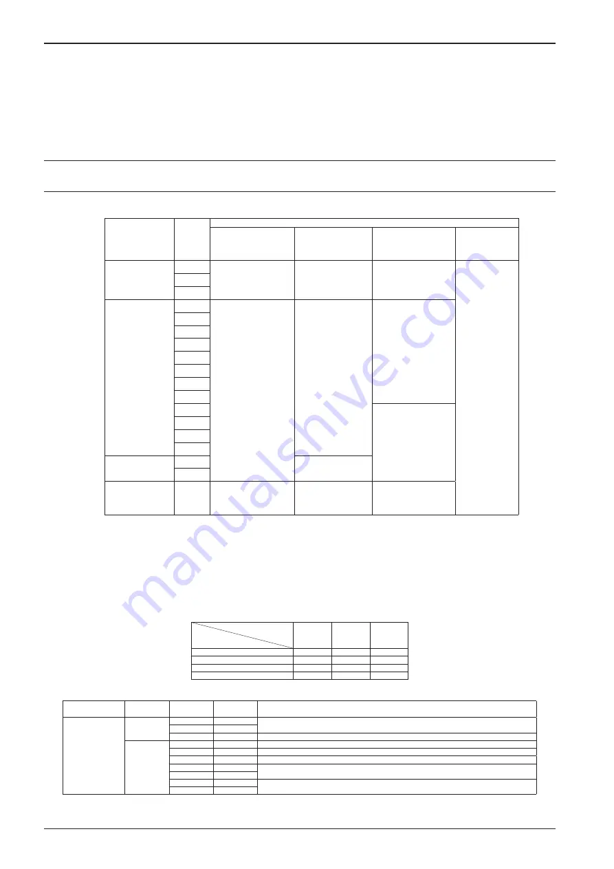
Recommended Cable
Item
Label
Minimum Recommended Cable Specifications
Rating Voltage/
Allowable Current
(at 86°F)
Cross-section
Solderless
Terminals
Maximum
Operating
Temperature
Power
L (+)
300V, 2A
14 to 16 AWG
R-type, 0.32 in.
Size: M4
140°F
N (–)
GND
Signal
A1 (+)
100V, 0.1A
14 to 18 AWG
R-type, 0.28 in.
Size: M3
A1 (–)
A2 (+)
A2 (–)
P1 (+)
P1 (–)
P2 (+)
P2 (–)
S.I. (+)
N/A
(screwless terminal)
S.I. (–)
S.O. (+)
S.O. (–)
Communication
I/O (+)
18 AWG
I/O (–)
External Ground
N/A
600V, 40A
12 AWG
Direct wiring or
solder-less terminal
(R-type, 8.1 mm)
1. Select the cable size to be used with the number of signals.
2. If the ambient temperature is 113°F or higher, use a cable resistant to 158°F or higher.
Recommended Cable for Modbus Communications
For Modbus communications, use a 0.75 mm
2
twisted-pair cable with a maximum cable length of 1200 m, depending on
operation environment.
Applicable Rubber Packing Size by Wire Gauge and Number of Conductors
Use shielded cables and refer to the following table for applicable rubber packing size(s):
Recommended Wire Size
Cable Packing Gum I.D.
14 AWG
16 AWG
18 AWG
10.1 to 11.0
2
3, 4
6, 7
11.1 to 12.0
3, 4
5
8
12.1 to 13.0
5
6
10, 12
13.1 to 14.0
6
7, 8
—
TERMINAL IDENTIFICATION OF SEPARATELY-MOUNTED TRANSMITTER
Item
Terminal
Name
Terminal
Number
Terminal
Color
Description
Sensor unit-
to-transmitter
interconnect cable
(200 m maximum)
TB20
1AB
BRN
Flow tube drive output
2AB
RED
3AB
BLK
BRN/RED, GRN/WHT, BLU/GRY, PUR/ORG/YEL shielded cables, bundled
TB21
1AB
PUR
Temperature input (inner)
2AB
ORG
Temperature input (outer)
3AB
YEL
Temperature input
4AB
BLU
Right-position pick-off sensor input
5AB
GRY
6AB
WHT
Left-position pick-off sensor input
7AB
GRN
1. Maximum cable length for PRO Series is 5 meters.
Summary of Contents for CamCor CC001
Page 14: ...14 CamCor CT and PRO Series Hardware Manual Section 3 This page is left blank intentionally ...
Page 24: ...24 CamCor CT and PRO Series Hardware Manual Section 3 This page is left blank intentionally ...
Page 54: ...54 CamCor CT and PRO Series Hardware Manual Section 5 This page is left blank intentionally ...
Page 62: ...62 CamCor CT and PRO Series Hardware Manual Section 7 This page is left blank intentionally ...


