background image

ITALIANO

Pag. 2

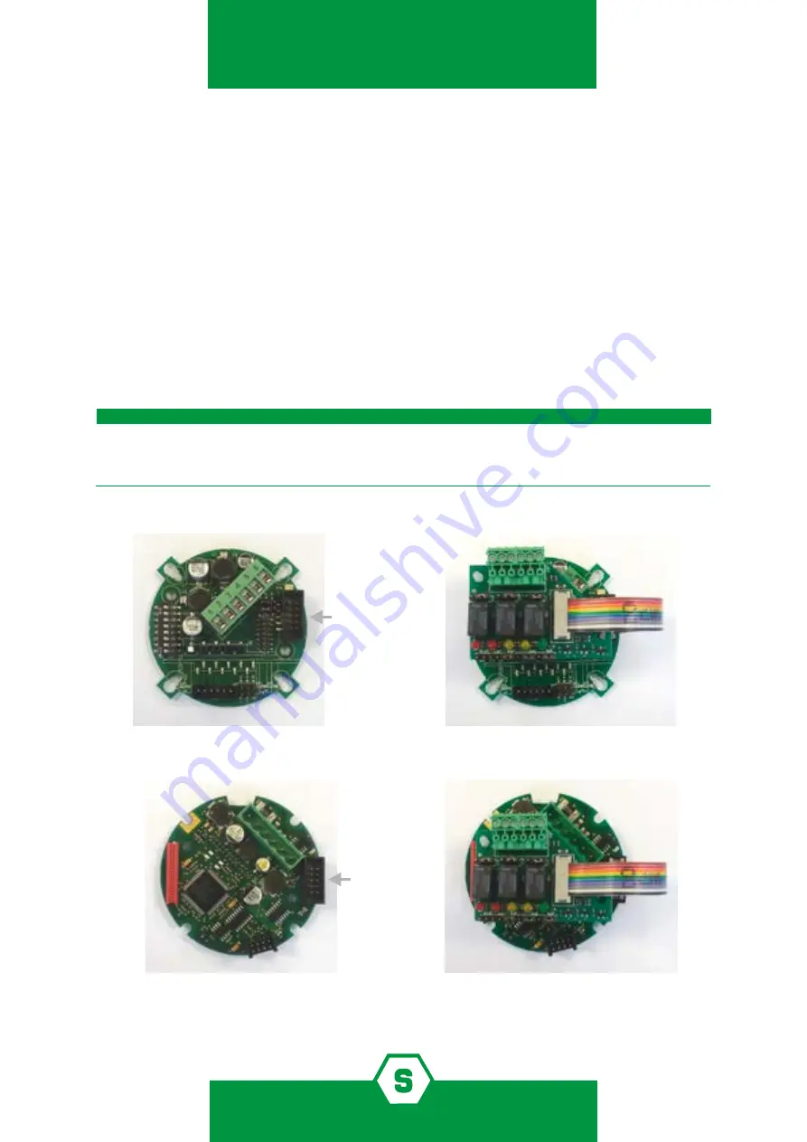
Figura 1)  Montaggio scheda relé sulla scheda SMART3

Figura 2)  Montaggio scheda relé sulla scheda SMART S

4.  Montaggio

1.  Il montaggio della STS3REL deve essere effettuato con il rilevatore spento. Inserire le 

colonnine nei fori presenti sul circuito base del rilevatore dove indicato. 

2.  Inserire il connettore posto all’ estremità del cavo flat della scheda 3 relè nel connet-

tore apposito presente sulla base dello SMART; rivolgere la sporgenza presente sul 
connettore verso l’ interno del circuito. Vedere figure 1 e 2.

3.  Avvitare le viti sulle colonnine in modo da fissare la scheda relè. Ultimato il montaggio 

si noterà che la morsettiera è rivolta verso l’alto, ossia verso la morsettiera del rilevatore

4.  Effettuare i cablaggi.
5.  Accendere il rilevatore.

Per i rivelatori della serie SMART3: per il corretto funzionamento della scheda STS3REL, è 

necessario aprire il jumper JP5-6 posizionato sulla scheda base del rivelatore (vedi manuale 

SMART3).

IMPORTANTE!

Summary of Contents for STS3REL

Page 1: ...uale d istruzione Instruction Manual MT3678 Rev 6 02 05 2022 2022 SENSITRON S R L All rights reserved www sensitron it Scheda a tre rel per SMART3 e SMARTS Three relay card for SMART3 and SMARTS STS3R...

Page 2: ...for any additional information relative to use or repair QUESTO MANUALE DEVE ESSERE LETTO ATTENTAMENTE DATUTTI COLORO CHE HANNO O AVRANNO LA RESPONSABILITA DI INSTALLARE UTILIZZARE O DI PRESTARE UN S...

Page 3: ...ano English SUMMARY 1 Introduction 3 2 Technical specifications 3 3 Layout and configuration 3 4 Assembly 4 SOMMARIO 1 Introduzione 1 2 Caratteristiche tecniche 1 3 Layout e configurazione 1 4 Montagg...

Page 4: ...nte energizzati Durante l installazione deve essere collegato all uscita di ogni rel un fusibile a 1 33 A Verificare il funzionamento dei contatti rel almeno una volta all anno testando il rile vatore...

Page 5: ...nnet tore apposito presente sulla base dello SMART rivolgere la sporgenza presente sul connettore verso l interno del circuito Vedere figure 1 e 2 3 Avvitare le viti sulle colonnine in modo da fissare...

Page 6: ...llation step connect a 1 33A fuse to each relay s output Check the relays functionality at least one time per year by testing detector response with gas application and checking the relays activation...

Page 7: ...Beware that the black triangle on the female connector corresponding to pin one is facing towards the internal part of the PCB 4 Tighten the card to the supports with the screws of the relay card 5 O...

Page 8: ...actdetails SENSITRONs r l Viale della Repubblica 48 20007 Cornaredo MI Italy TEL 39 0293548155 FAX 39 0293548089 www sensitron it E mail sales sensitron it LEADER IN SIL2 SIL3 FIXED GAS DETECTION SYST...

Reviews: