background image

4

5

1

2

5

6

7

8

1

2

3

4

4

1

2

3

3

GREEN

BROWN

WHITE

YELLOW

PINK

VIOLET

RED

BLUE

WHITE/RED

WHITE/BLUE

POWER 
POWER SUPPLY  -

RELAY 1 - FIELD 1

RELAY 2 - FIELD 2

TEST +
TEST  -

TEACH-IN

No monitoring*: 

connect red and blue wires to power supply (no polarity)

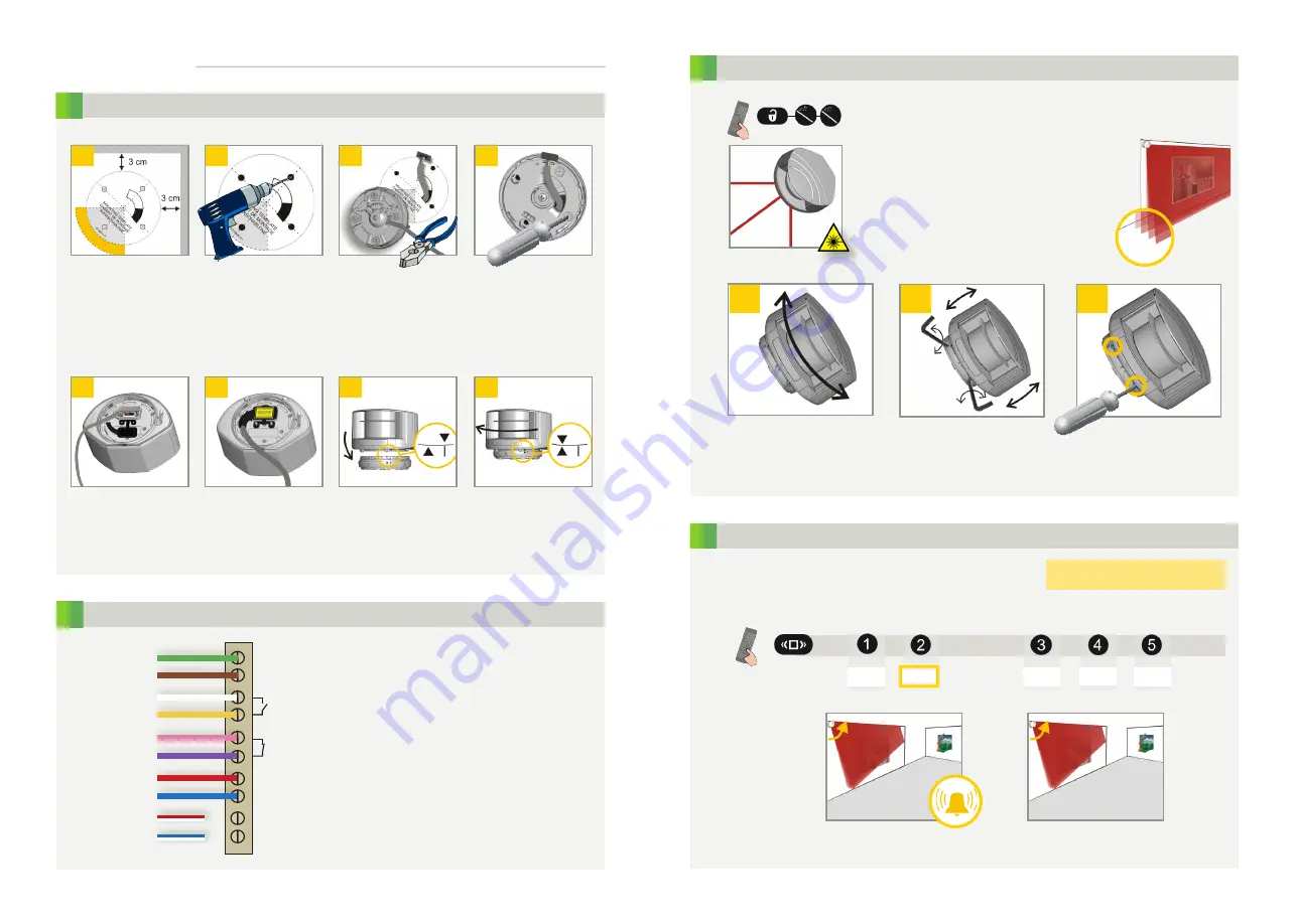
MOUNTING

WIRING

Use the adhesive 

mounting template 

to position the sensor 

correctly. The grey area 

indicates the detection 

range.

Drill 4 holes as indicated 

on the mounting 

template. Make a hole 

for the cable if possible.

Pass the cable +/- 10 cm 

though the cable opening. 

If drilling an opening is 

not possible, use the cable 

conduits on the back side of 

the bracket.

Position the bracket 

and fasten the 4 screws 

firmly.

Open the protection 

cover, plug the 

connector and position 

the cable in the slit.

Close the protection 

cover and fasten it firmly.

Turn the sensor until the 

two triangles are face 

to face.

Position the housing on 

the bracket.

*for more info, please contact SENSORIO

INSTALLATION STEPS

No teach-in via input*: 

connect white/red and white/blue wires to ground

left

right

MOUNTING SIDE

Stay outside of the detection 

field to avoid disturbances.

Select the corresponding mounting side.

The sensor then learns its environment and automatically 

determines the detection field(s). Both red LEDs flash slowly and 

the 3 visible laser beams automatically light up during 30 seconds.

WITH BACKGROUND

WITHOUT BACKGROUND

The sensor memorizes the floor as reference point 

and will signal a fault in case the orientation of the 

sensor is changed (on purpose or by accident).

No reference point is memorized, 

no alarm in case of interference 

with sensor position.

Adjust the lateral position of 
the detection field.

Adjust the tilt angle of the 

detection field with the hex 

key.

Lock the position of the 

mounting bracket to avoid 

malfunctioning in case of 

extreme vibrations.

Unlock the sensor and activate the visible laser beams.

The visible laser beams indicate approximately 
the postion of curtain C1 and limit the angle of 
the detection field.

The visible laser beams stay activated for 

15 minutes or can be turned off the same way 

they were activated.

POSITIONING

left

right

centre

C1

C2

C3

C4

Summary of Contents for LZR-S25

Page 1: ...1 LZR S25 LASER SCANNER FOR BUILDING AUTOMATION AND SECURITY EN User s Guide for product version 0600 and more ...

Page 2: ...er wavelength 650nm max output CW power 3mW Class 3R according to IEC 60825 1 The visible laser beams are inactive during normal functioning The installer can activate the visible lasers if needed CAUTION Use of controls adjustments or performance of procedures other than those specified herein may result in hazardous radiation exposure Do not look into the laser emitter or the visible red laser b...

Page 3: ...connect white red and white blue wires to ground left right MOUNTING SIDE Stay outside of the detection field to avoid disturbances Select the corresponding mounting side The sensor then learns its environment and automatically determines the detection field s Both red LEDs flash slowly and the 3 visible laser beams automatically light up during 30 seconds WITH BACKGROUND WITHOUT BACKGROUND The se...

Page 4: ...ntrol use the following sequence no field 0 1 m 25 0 m 0 1 m 25 0 m 0 1 m 25 0 m REMOTE CONTROL ADJUSTMENTS OPTIONAL FACTORY VALUES IMMUNITY FILTER MIN OBJECT SIZE OUTPUT CONFIGURATION DETECTION FIELD REDIRECTION approximate values A active P passive NO normally open NC normally closed UNCOVERED ZONE field 1 field 2 field 2 field 1 or field 2 off indoor outdoor low outdoor med outdoor high indoor ...

Page 5: ...rol the sensor locks the access to the remote control session The batteries in the remote control are not installed properly or dead The remote control is badly pointed A reflective object is in close proximity to the sensor You have to enter a code or the wrong code was entered The object size is too small The polarity of the power supply is inverted Check cable and connexion Check wiring The red...

Page 6: ... free 35 V DC 24 V AC 80 mA resistive tON 5 ms tOFF 5 ms typ 30 Ω 0 7 V 20 mA 10 µA 2 optocouplers galvanic isolated polarity free 30 V DC over voltage protected Log H 8 V DC Log L 3 V DC 5 ms 1 blue LED power on status 1 orange LED error status 2 bi coloured LEDs detection output status green no detection red detection 125 mm D x 93 mm W x 70 mm H mounting bracket 14 mm PC ASA black or white 45 0...

Reviews: