8
9
x
4
2
1
3
x
1
1
1
1
1
2
3
1
2
3
1
1
1
1
1
1
1
1
1
1
2
1
1
1
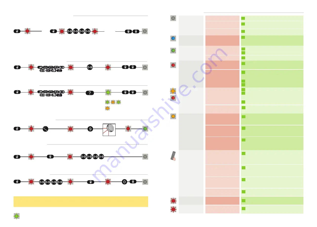
HOW TO USE THE REMOTE CONTROL
30 minutes after last use, the sensor locks the access to the remote control session.
Cut and restore power supply. The remote control session is accessible again during 30 minutes.
ADJUSTING ONE OR MORE PARAMETERS
CHECKING A VALUE
RESTORING TO FACTORY VALUES
SAVING AN ACCESS CODE
DELETING AN ACCESS CODE
The access code is recommended for sensors installed close to each other.
After unlocking, the red
LED flashes and the sensor
can be adjusted by remote
control.
If the red LED flashes quickly after unlocking, you
need to enter an access code from 1 to 4 digits.
X = THE NUMBER OF FLASHES INDICATES THE VALUE OF THE PARAMETER.
= field width: 4.2 m
= field width is defined by teach-in
To end an adjustment session,
always lock the sensor.
Enter the existing code
teach-in
TROUBLESHOOTING
No blue LED
Only the blue LED
is on.
The detection LED
remains green.
The orange LED is
flashing and the
detection LEDs are
red.
The detection LED
remains red.
The orange LED
is on.
The sensor does
not respond to the
remote control.
The sensor does
not unlock.
There is no power.
The test input is not
connected.
The detection field is too
small or deactivated.
Someone or something is
in the detection field.
The field is touching the
floor, the wall or the door,
which leads to detection.
No background (reference
point) is found.
The sensor is masked.
The power supply voltage
is exceeding the acceptable
limits.
The sensor exceeds its
temperature limits.
Internal error
30 minutes after last use
of the remote control, the
sensor locks the access to
the remote control session.
The batteries in the remote
control are not installed
properly or dead.
The remote control is badly
pointed.
A reflective object is in close
proximity to the sensor.
You have to enter a code or
the wrong code was entered.
The object size is too small.
The polarity of the power
supply is inverted.
Check cable and connexion.
Check wiring.
The red and blue cable have to be connected
to the test input or the power supply.
Check the size of the fields.
Launch a teach-in.
Step out of the field and/or remove the any
object(s) from the field.
Activate the 3 red beams and check if the
position of the sensor is correct.
If not, adjust the hex screws.
Verify the field size.
Launch a teach-in.
Check the position of the sensor.
Check the mounting side setting.
If there is no background, set the mounting side
to value 3 to 5.
Launch a new teach-in.
Verify and clean the front screens
with a damp cloth.
Check the power supply voltage.
Verify the outside temperature where the sensor
is installed. Eventually protect the sensor from
sunlight using a cover.
Wait a few seconds.
If the LED remains ON, reset the power supply.
If the LED turns on again, replace the sensor.
Cut and restore power supply.
The remote control session is accessible again
during 30 minutes.
Verify or replace the batteries.
Point the remote control towards the sensor,
but with a slight angle. The RC should not be
pointed in a right angle in front of the sensor.
Avoid highly reflective material in proximity to
the sensor.
Please contact SENSORIO.
Check the polarity of the power supply.
Decrease the min. object size.
All LEDs have been de-
activated by remote control.
Activate the LEDs by remote control.
The red LED flash
Under the RC state
Quit the RC state, press 2x lock.


