background image

Conquest 2-Assembling 

Conquest

3

 2

Assembling Conquest

2.1

Basic Assembly

Use the following steps to assemble the Conquest unit:

1. Undo the 4 plastic latches that secure the lid of the Conquest carry case and open the 

lid.

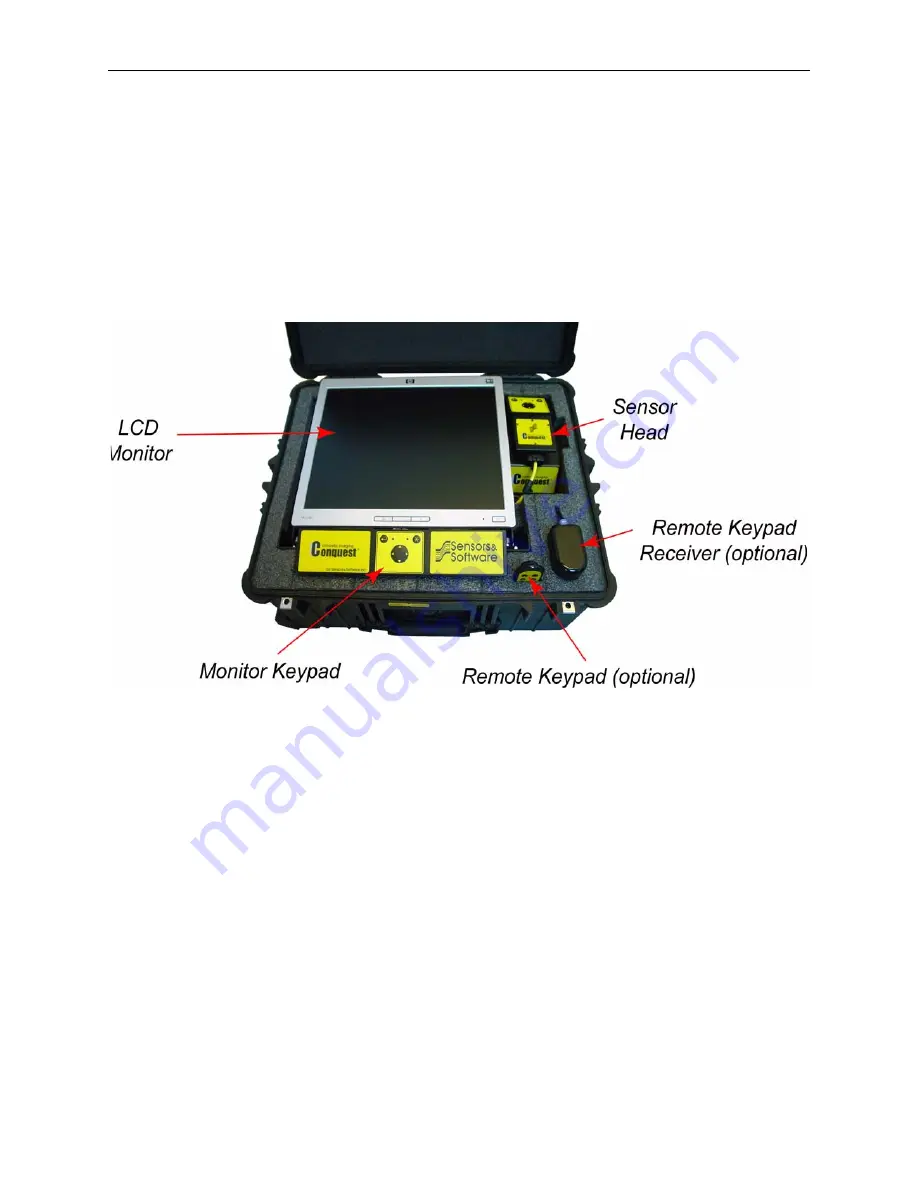
 Figure 2-1:The main components of a Conquest system.

2.The LCD monitor is held on a piston-hinged frame that can be raised and lowered to

hold the monitor at any angle for viewing. Gently pull up the edge of the monitor to the
desired angle.

3. The Conquest system will have 3 or 4 cables, depending on options.  These cables

are stored in the deeper storage area under the monitor.  Identify the following cables:

a) System power cable with AC plug

b) LCD power cable with AC plug

c) Yellow cable attached to the Sensor Head

d) Cable to the Remote Receiver (optional)

Summary of Contents for Conquest Series

Page 1: ... Copyright 2012 Sensors Software Inc Drawing Number 2006 00112 05 ...

Page 2: ......

Page 3: ......

Page 4: ......

Page 5: ...OFTWARE PRODUCT for backup purposes in support of your use of the product on a single workstation You may not copy distribute or sell copies of the SOFTWARE PRODUCT or accompanying written materials including modified or merged SOFTWARE PRODUCT to others sell licence sublicence assign or otherwise transfer this licence to anyone without the prior written consent of S S modify adapt translate decom...

Page 6: ...e or misapplication S S shall have no responsibility to replace the SOFTWARE PRODUCT refund the licence fee or replace or repair the HARDWARE PRODUCT Do not tamper with any PRODUCT PRODUCT contains no user serviceable parts If tampering is evident in S S s opin ion warranty is void and null No oral or written information or advice given by S S its dealers distributors agents or employees shall cre...

Page 7: ...ritten between the parties relating to the subject matter of this agreement Should you have any questions concerning this agreement please contact in writing Sensors Software Inc 1040 Stacey Court Mississauga Ontario Canada L4W 2X8 Tel 905 624 8909 Fax 905 624 9365 Web www sensoft ca E mail sales sensoft ca pulseEKKO Noggin SpiView SnowScan Conquest SmartCart SmartHandle RoadMap Conquest for Windo...

Page 8: ......

Page 9: ...epth 15 4 6 Power Cable Detection PCD Principles 16 5 Line Scans and Grid Scans 21 5 1 Step 1 Define Area of Interest 21 5 2 Step 2 Use Line Scan mode to get main structure orientation 22 5 3 Step 3 Place grid mat 23 5 4 Step 4 Grid Scan Parameters 24 5 5 Step 5 Surveying on the Grid 24 5 6 Step 6 Calibrate the Concrete Type 25 5 7 Step 7 Depth Slice Image Computation 25 5 8 Step 8 Working with De...

Page 10: ...er Supply 41 9 3 Warning Beep in Line Scan Mode 41 9 4 Warning Beep and Flashing in Grid Scan Mode 41 9 5 Sensor Head Key Pad Doesn t Respond 42 9 6 Remote Keypad Doesn t Work 42 9 7 System Does Not Start with the Sensor Head or Remote Keypads 42 9 8 Nothing Displayed on Monitor 42 9 9 Power Light on Monitor Keypad Not Illuminated 42 9 10 Export Menu Item Not Accessible 43 9 11 PCD Menu Item Not A...

Page 11: ... GPR Emissions Interference and Regulations B 1 B 1 FCC Regulations USA B 2 B 2 ETSI Regulations for the EC European Community B 6 B 3 Industry Canada Regulations B 7 Appendix C Instrument Compatibility C 1 Appendix D Safety Around Explosive Devices D 1 Appendix E Conquest Glossary E 1 ...

Page 12: ...Table of Contents Conquest iv ...

Page 13: ...ompact Flash disk and PC software Conquest provides quick easy surveying with integrated analysis and 3D imaging Conquest Enhanced provides extended capability of data transfer to a PC and Windows based software for further enhancement and image export for reports The PCD Power Cable Detector uses an additional sensor built inside the Conquest sensor head to detect and image current carrying cable...

Page 14: ...1 Overview Conquest 2 ...

Page 15: ...itor is held on a piston hinged frame that can be raised and lowered to hold the monitor at any angle for viewing Gently pull up the edge of the monitor to the desired angle 3 The Conquest system will have 3 or 4 cables depending on options These cables are stored in the deeper storage area under the monitor Identify the following cables a System power cable with AC plug b LCD power cable with AC ...

Page 16: ...n the Monitor Keypad will illuminate Cables C and D should already be connected 5 Figure 2 3 shows all the cables and connections in the back of Conquest system All these connections should already in be in place but check to make sure that they are secure Also check that the connection to the Sensor Head is tight Figure 2 3 Cable connections in the back of the Conquest system ...

Page 17: ... lid tilted down over the back of the monitor to minimize the amount of dust settling in ventilation slots 2 2 Attaching the Handle Conquest Enhanced comes with a handle to allow the operator to stand up during data collection on floors Retract the spring loaded knobs on the end of the handle align with the two holes at the back of the Sensor Head and release them to lock into position Figure 2 4 ...

Page 18: ...onal Compact Flash card make sure the system is powered down tilt the monitor down into its storage position tilt up the Monitor Keypad and insert the card into the card slot Data are always saved to the internal memory but when a removable card is present the data can be copied to the removable card using the Export function accessible from the Tools menu Figure 2 6 The Compact Flash card slot is...

Page 19: ... is lowered into its storage position 4 Ensure that the optional Remote Receiver Cable runs inside the foam channel cut out so it is not damaged when the monitor is lowered into its storage position 5 Carefully lower the LCD monitor into its storage position and close the lid of the carry case securing the 4 plastic latches 6 The carry case has wheels and an extendable handle so the Conquest syste...

Page 20: ...3 Packing Up Conquest Conquest 8 ...

Page 21: ... conduits and other targets embedded inside The GPR display shows signal amplitude versus depth time and sensor position along a line This is called a Line Scan The echo sounder and fish finder used on boats operate in an analogous fashion as indicated in Figure 4 2 Figure 4 2 GPR is conceptually similar to a fish finder GPR is just like a fish finder echo sounder sends out a ping signal scattered...

Page 22: ...igure 4 4 The sensor should cross perpendicular to the long axis of the feature i e we must cross the feature at 90o Figure 4 3 Figure 4 3 The arrow represents the path of the sensor crossing the rebar or conduit at 90o When the sensor crosses a target we get the typical hyperbolic or inverted V response from the target as shown in Figure 4 4 A real data image is shown in Figure 4 5 Figure 4 4 Cro...

Page 23: ...of the hyperbola Figure 4 4 and Figure 4 5 is controlled by the Concrete Type property which is a measure of the velocity the Conquest signals travel through the particular concrete For reliable depth estimates and accurate depth slice images the user must calibrate the unit on each site to extract the concrete type The Concrete Type can be extracted from the data by calibrating after collecting a...

Page 24: ...bar perpendicularly The image also shows flat lines generated by running the sensor parallel along the top of a rebar and the bot tom of concrete Ensure that the Filter option is OFF or flat lying features are removed from the image Be aware that Conquest has the option of applying a background subtraction filter to the data to remove flat lying features in the data image The filter option is avai...

Page 25: ...are based on collecting multiple line scans in two directions on a grid Together these line scans sample a 3D volume or cube of concrete This is shown conceptually in Figure 4 11a Processing the data results in a solid data volume again conceptually shown in Figure 4 11b Figure 4 11 a A series of lines scans on a grid cover a volume b Processing interpolates data into the gaps between lines to pro...

Page 26: ...1 inch thick depth slices 4 5 Limitations Before using the Conquest system keep in mind that Conquest won t solve every problem that you will face 4 5 1 New Concrete Most importantly Conquest will not work effectively on very new concrete When concrete is very fresh it absorbs the signals that the Conquest system emits and does not allow penetration to substantial depths Depending on the concrete ...

Page 27: ...o waves to image the subsurface These waves are strongly absorbed by the material being scanned The material type and pore water salinity dictate how deep signals will penetrate Concrete can be highly variable depending on the original mix and state of wetting Figure 4 13 shows how the depth of penetration can vary with concrete type Figure 4 13 Concrete absorbs GPR signals and generally limits pe...

Page 28: ...the location of current carrying cables by detecting the magnetic field created by AC current flowing at 50 Hz or 60 Hz Figure 4 14 Depiction of the magnetic field created by a current flowing in a wire Figure 4 15 The Conquest detects the current carrying cable best when crossing it perpendicularly ...

Page 29: ...ears after collecting each line in a Grid Scan Figure 4 17 After Grid Scan data have been processed into depth slice images the PCD image can also be displayed The magnetic field generated by current flowing in wires can be simple or highly contorted depending on how the wires are oriented Examples of simple and twisted wires are shown in Figure 4 18 ...

Page 30: ...Operation Conquest 18 Figure 4 18 The shape of the magnetic field generated can be simple or complex depending on whether the wires are straight vertically or horizontally oriented their spacing and the dgree of twist ...

Page 31: ...nse can vary over a wide range typically from double digits to 10 000 or more Figure 4 19 Figure 4 19 The strength of the magnetic field generated depends on the nature of the wire single wire pair or twisted pair and the spacing It also depends on the depth of the wire and amount of current flowing in the wire PCD values can vary over a wide range depending on these factors ...

Page 32: ...4 Principles of Operation Conquest 20 ...

Page 33: ...mperial units The five grid sizes available are 1 24 x 24 or 600mm x 600mm 2 48 x 48 or 1200mm x 1200mm 3 24 x 48 or 600mm x 1200mm 4 96 x 96 or 2400mm x 2400mm 5 24 x 96 or 600mm x 2400mm Details on setting the parameters for Grid Scans are described in Help Grid Scan Define Parameters Your specific site will dictate what is practical and where you can operate Obviously in tight corners and space...

Page 34: ... It is best to go at a uniform slow speed rather than going fast and jerky because irregular motion may reduce data quality Line Scan data are saved to a maximum line length of approximately 6 4m 21 feet If a Line Scan is longer than this length only the last 6 4m 21 feet is saved Backup Indicator Line Scan mode incorporates a unique backup feature Move the sensor backwards and an arrow on the scr...

Page 35: ... then place the grid mat registration point on that mark The best way to do that is to put a chalk mark or pin or other indicator on the surface and then place the transparent grid mat over top of it This reference point should be such that you can go back to the site after you have removed the grid mat The transparent grid mat should be taped on to the structure with duct tape During grid scan co...

Page 36: ...ric lines provides a grid coordinate system This same coordinate system shows up on the images created by Conquest for easy reference back to the grid 5 4 Step 4 Grid Scan Parameters Once you have your grid mat in place you are now ready to acquire Conquest data To do this you need to set up some parameters Details on setting the parameters for Grid Scans are described in Help Grid Scan Define Par...

Page 37: ...f the grid is obstructed so not all the lines can be collected Small grids can usually be processed in less than one minute Larger grids may take several minutes Details on generating Depth Slice images are described in Help Grid Scan View the Results It is not necessary to reprocess data every time you want to view it Once a grid has been processed the images are always immediately available by s...

Page 38: ...fined by the cross hairs on the depth slice Conceptually the cross section views are like looking at the sides of the cube see Figure 5 4 The best way to think of the depth slice images are as photograph like views from above The rectangular regions to the bottom and the right should be thought of as cross sections through the concrete in each direction at the positions of the cross hairs Figure 5...

Page 39: ...isplayed in the Slice View menu The menu makes it easy to toggle between the GPR Depth Slice images and the PCD image Unlike depth slice images the PCD image is a single image that is NOT associated with a specific depth range Notice that similar to GPR responses from rebar and other objects described above the PCD response are broad compared to the actual size of the cable so the width of the PCD...

Page 40: ...ta to a PC for further analysis This is available if you selected the enhanced system option or purchased the enhanced upgrade option after buying the base system Details on Exporting data are described in Help Tools 5 11 1 Compact Flash Drive Transfer Files collected with the Conquest system are saved to an internal drive but the Export feature copies data to an optional removable Compact Flash c...

Page 41: ...are like Voxler available from Sensors Software 5 11 3 Conquest Grid Parameter CV2 File Definition To display a Conquest grid scan in ConquestView the user must open the Conquest Grid Parameter file This file is saved in the same folder as the grid scan data and has a CV2 extension The name of the file is based on the following format MMDD_NNG CV2 where MM is the month 01 12 DD is day 00 31 NN is ...

Page 42: ...5 Line Scans and Grid Scans Conquest 30 ...

Page 43: ...onquest including menu navigation grid scans slice views line scans and system tools are all available by selecting the Help menu option from the main menu Figure 6 1 The Help screens are also available in Adobe Acrobat PDF and Microsoft PowerPoint PPT format on the Conquest Software CD for easy reference Figure 6 1 Accessing Help ...

Page 44: ...6 Help Conquest 32 ...

Page 45: ...conducted on the 5th floor of a medical building that was undergoing some renovations The grid size was 600x600mm normal resolution In Figure 7 1a we see rebar located between 60 90mm depth If we go deeper to 240 270mm Figure 7 1b there are two conduits running obliquely across the grid area In the slice immediately below that Figure 7 1c there are some features at numeric lines 4 6 a b c Figure 7...

Page 46: ...rmal resolution The main feature of this grid scan is the overlapping wire mesh seen prominently at adjacent depths The reason that it shows at 2 different depths is that the mesh dips in certain areas a result of the weight of the concrete as it was being poured From the pictures it can be seen that the mesh has a spacing of 200mm a b Figure 7 2 ...

Page 47: ...ngles to and directly beneath the mesh Figure 7 3b shows the bottom of concrete between 9 6 to 10 8 inches deep In this case it is slab on pan which is a metal support sheet on which concrete was poured during construction The radar waves can not penetrate metal and hence the signals are reflected entirely a b Figure 7 3 ...

Page 48: ...e a typical rebar pattern at a depth of 5 6 inches The PCD image Figure 7 4b reveals a strong magnetic field response that may be associated with the leftmost vertical rebar The interpretation is that a current carrying cable has been tied to the rebar a b Figure 7 4 ...

Page 49: ...r quality Dark Blue highest quality Figure 8 1 With DynaQ the colour of the progress bar indicates the quality of the data being collected Dark blue indicating the highest quality of data is achieved by moving the sensor head more slowly com pared to the speed for the light blue or yellow colors In general avoid collecting data at extremely high rates of speed The microcomputers are programmed to ...

Page 50: ...ast 6 4 m 21 feet is saved 8 5 Extending the Depth after Collecting Data The system always scans to a depth of approximately 3 feet or 1 meter regardless of the depth setting the user has selected on the system The user depth setting only controls the depth of data displayed on the screen The user can change the Depth menu item in Line Scan to see deeper data To see deeper in Grid Scan mode the us...

Page 51: ...rompted to run the System Test and re calibrate The IEP option ensures that Conquest always collects the highest quality data and displays the most accurate images The IEP option is found in the Tools menu and is automatically enabled when Conquest is turned on and is normally left on In fact if the IEP is turned off the user is informed on all Line Scan Grid Scan and Depth Slice screens As well t...

Page 52: ...n the IEP feature off and collect the data without it see Image Enhancement Processing 8 9 Odometer Wheel Calibration The odometer wheel calibration is done under Wheel Cal in Tools The odometer wheel should be periodically calibrated perhaps once a week or once a month It should also be re calibrated if you are collecting data on a different surface than usual for example on a textured floor rath...

Page 53: ...he system starts to beep there are 2 possible causes 1 The sensor head is being pushed too fast This happens most often when the Stretch Factor is large A high stretch value uses more computer resources for the screen display slowing data acquisition Reduce the Stretch value or simply slow down the speed of the Sensor Head to eliminate the warning If the beeping keeps occurring and you don t think...

Page 54: ...s been initialized The user must press any key on the monitor keypad to start the system 9 8 Nothing Displayed on Monitor Sensor head beeps at start up but nothing appears on the display monitor 1 Check the connections on the video cable on the control module 2 Check both ends of the power cable that connects to the monitor the plug on the monitor end is removable and can occasionally pull out dur...

Page 55: ...e powered down the card ejected all files removed from the card the card re installed the system powered up and Export attempted again 9 11 PCD Menu Item Not Accessible The PCD menu item under Tools will be greyed out and not accessible if the Conquest sensor head does not contain the PCD sensor 9 12 Constant Prompt to Perform System Test If the operator is constantly prompted to run the System Te...

Page 56: ...rs Software Inc 1040 Stacey Court Mississauga Ontario Canada L4W 2X8 Tel 905 624 8909 Fax 905 624 9365 E mail sales sensoft ca When contacting Sensors Software Inc please have the following information available 1 System Serial Number This is found by tilting up the Monitor Keypad 2 Version number of the data acquisition software 3 The error number or message appearing 4 A brief description of whe...

Page 57: ... in use they should be placed in their storage box 10 2 Conquest Sensor Head Wear Pad The bottom of the Sensor Head is covered with a wear resistant skid pad The skid pad is designed to take the majority of the abrasive wear If the pad wears down enough the less resistant plastic housing may start to wear If this occurs it is best to replace the skid pad It is easily removed and a new one can be p...

Page 58: ...10 Care and Maintenance Conquest 46 ...

Page 59: ...res and time duration specified by the FCC and OSHA vary with excitation frequency The lowest threshold plane wave equivalent power cited is 0 2 mW cm2 for general population over the 30 to 300 MHz frequency band All other applications and frequencies have higher tolerances as shown in graphically in Figure A A 1 Figure A 1 FCC limits for maximum permissible exposure MPE plane wave equivalent powe...

Page 60: ...ns many references and web sites 2 Evaluation Compliance with FCC Guidelines for Human Exposure to Radio Frequency Electromag netic Fields USA Federal Communications Commission Office of Engineering Technology OET Bulletin 56 Contains many references and web sites 3 USA Occupational Safety and Health Administration regulations paragraph 1910 67 and 1910 263 Web Sites www fcc gov Bureau Engineering...

Page 61: ... GPR instruments are considered to be UWB ultra wideband devices The regulatory regimes worldwide are devising new rules for UWB devices Sensors Software Inc maintains close contact with the regula tors to help guide standard development and assure that all products conform You should continually monitor the News link on our website www sensoft ca for updates on standards Electronic devices have n...

Page 62: ...eral devices constitutes a Change or Modification out lined in the warning above Operating Restrictions Operation of this device is limited to purposes associated with law enforcement fire fighting emergency rescue scientific research commercial mining or construction Parties operating this equipment must be eligible for licensing under the provisions of Part 90 of this chapter FCC Interpretation ...

Page 63: ...resulting from this coordination b The users of UWB imaging devices shall supply operational areas to the FCC Office of Engineering and Technology which shall coordinate this information with the Federal Government through the National Telecommunications and Information Administration The information provided by the UWB operator shall include the name address and other pertinent contact informatio...

Page 64: ...tion shall be submitted to the FCC following the procedure in paragraph b of this section f The coordination of routine UWB operations shall not take longer than 15 business days from the receipt of the coordination request by NTIA Special temporary operations may be handled with an expe dited turn around time when circumstances warrant The operation of UWB systems in emergency situa tions involvi...

Page 65: ...TACT NAME AND PHONE NUMBER AREA OF OPERATION COUNTIES STATES OR LARGER AREAS FCC ID E G QJQ CONQ DE1 EQUIPMENT NOMENCLATURE E G CONQUEST DE Send the information to Frequency Coordination Branch OET Federal Communications Commission 445 12th Street SW Washington D C 20554 ATTN UWB Coordination Fax 202 418 1944 INFORMATION PROVIDED IS DEEMED CONFIDENTIAL ...

Page 66: ...d information they should acquire copies of the following docu ments available from ETSI ETSI EN 302 066 1 V1 2 1 February 2008 Electromagnetic compatibility and Radio spectrum Matters ERM Ground and Wall Probing Radar applications GPR WPR imaging systems Part 1 Technical characteristics and test methods ETSI EN 302 066 2 V1 2 1 February 2008 Electromagnetic compatibility and Radio spectrum Matter...

Page 67: ...ruction companies and emergency rescue or firefighting organizations Should the ground penetrating radar be used in a wall penetrating mode then the following restriction should be noted by the user 1 This In wall Radar Imaging Device shall be operated where the device is directed at the wall and in contact with or within 20 cm of the wall surface 2 This In wall Radar Imaging Device shall be opera...

Page 68: ... of electromagnetic fields such as TV stations radio stations and cell phones can cause signals detectable by a GPR which may degrade the quality of the data that a GPR device records and displays Such additive signal is unavoidable but sensible survey practice and operation by an experienced GPR practitioner can minimize such problems In some geographic areas emissions from external sources may b...

Page 69: ...Appendix C Instrument Compatibility Conquest C 2 ...

Page 70: ...s we recommend keeping the GPR transmitters at least 5 feet 2m from blast ing cap leads as a precaution Some customers do experimental trials with their particular blasting devices to confirm with safety We strongly recommend that GPR users routinely working with explosive devices develop a systematic safety methodology in their work areas The UXO issue is more complex and standards on fuses do no...

Page 71: ...Appendix D Safety Around Explosive Devices Conquest D 2 ...

Page 72: ...uest display Depth Slice is the term to describe the Conquest data acquired between two depths top of depth slice and bottom of depth slice Most often a grid scan has the scan depth subdivided into a number of depth slices Slice or Depth Slice Image is the term used to describe the Conquest data in a depth slice when the data are displayed as a computer generated image This term will normally be s...

Page 73: ...ction and alpha betical line names in the other direction Conquest depth slice images can be formed from numeric alpha or combined numeric and alpha combo Combo slices are the standard but sometimes advanced users can benefit from viewing alternate slice types Numeric Slice depth slice image created from numerically named lines in a Conquest grid scan Alpha Slice depth slice image created from alp...

Page 74: ...plied to the process of automatically displaying Conquest Help slides with a timed delay Color Bar the bar of colors which display the colour palette on the Conquest Color menu items Colors to the left represent strong negative signals and colors to the right indicate strong positive signals Colors in the middle represent weak signals 3D View the term used in Conquest where depth slices and cross ...

Page 75: ...Conquest Appendix E Conquest Glossary E 4 ...

Reviews: