7-SmartHandle Configuration Assembly (Noggin 500 & 1000 only)
Noggin
34
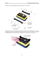
Figure: 7-5 Press the handle base straight down onto the four, silver mounting posts. The handle base
should be pushed all the way down onto the odometer bracket. Insert the four quick-release pins to secure
the handle.
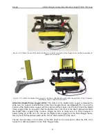
Figure: 7-6 The full-length SmartHandle is shown in Figure 7-1. The SmartHandle can be shortened by
removing the center handle section using the thumb-screws. Use the Velcro straps to secure the cable
onto the SmartHandle, ensuring there is excess cable near the connection at the Noggin to allow the
SmartHandle to pivot up and down without straining the cable.
Velcro Strap
Summary of Contents for Noggin 100
Page 1: ...User s Guide Copyright 2012 Sensors Software Inc 2011 00022 02 Noggin ...
Page 2: ......
Page 4: ......
Page 8: ......
Page 17: ...Noggin 2 Noggin Components 3 Figure 2 3 Noggin 100 components ...
Page 156: ...Appendix D Instrument Interference Noggin D 2 ...
Page 158: ...Appendix E Safety Around Explosive Devices Noggin E 2 ...
Page 162: ...Noggin G 4 ...


