
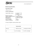
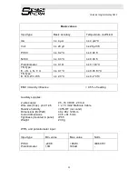
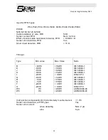
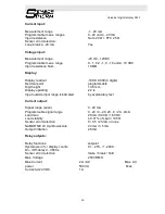
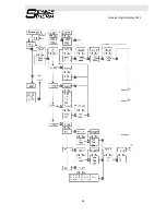
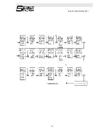
Universal digital display AZ12
4
GerneralWarning!
This modul is designed for connection to hazardous electricvoltages. Ignoring this
warning can result in severe personalinjury or mechanical damage. To avoid the risk
of electric shock and fire, the safety instructions of this manual mustbe observed and
the guidelines followed. The specificationsmust not be exceeded, and the module
must only be appliedas described in the following. Prior to the commissioning of
the module, this manual must be examined carefully. Onlyqualified personnel
(technicians) should install this module.If the equipment is used in a manner not
specified by themanufacturer, the protection provided by the equipment
may be impaired.
Harzadous Voltage Warning!
Until the module is fixed, do not connect hazardousvoltages to the module.
The following operations should only be carried out on adisconnected
module and under ESD safe conditions:
troubleshooting the module.
Repair of the module must be done by Sensortherm GmbH only.
Symbol identification:
Triangle with an exclamation mark: Warning / demand.
Potentially lethal situations.
The CE mark proves the compliance of the module with the essential
requirements of the directives.


