background image

4-6

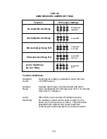
Table 4-2

03RM RECEIVER JUMPER SETTINGS

Function

JP9 Jumper Settings

No Audio/No Aux Relay

Std Audio/No Aux Relay

Std Audio/Aux Relay N.O.

Std Audio/Aux Relay N.C.

Audio Switching/
No Aux Relay

A    B    C     D

H   G     F     E

A    B    C     D

H   G     F     E

A    B    C     D

H   G     F     E

A    B    C     D

H   G     F     E

A    B    C     D

H   G     F     E

No Jumpers
Installed

Jump A-B

Jump A-B,
C-D, H-G

Jump A-B,
C-D, G-F

Jump A-H,
B-C

Function Definitions:

Standard

Audio:

Auxiliary

Relay:

Audio

Switching:

Audio signal is always available at audio terminal

of 03RM receiver.

Auxiliary alarm relay contacts actuate with alarm

relay; configurable for normally open (N.O.) or normally

closed (N.C.) operation.

When PAS zones consist of multiple receivers,

the auxiliary contact can be used to switch on the

audio only for the receiver in alarm.  This eliminates

possible audio clutter which could result from

combining the audio signals from several receivers.

Summary of Contents for 03RM

Page 1: ...03RM Personal Alarm System T0DA0202 001 Rev A First edition September 15 2009 03RM Installation Operation Guide ...

Page 2: ...n to the best of its ability Senstar Corporation is not responsible for any damage or accidents that may occur due to errors or omissions in this guide Senstar Corporation is not liable for any damages or incidental consequences arising from the use of or the inability to use the software and equipment described in this guide Senstar Corporation is not responsible for any damage or accidents that ...

Page 3: ... or materials This warranty shall not apply to any products which have been installed repaired or altered by other than personnel certified by the Company or to products which have been subject to physical or electrical abuse misuse or improper storage or to products which have not been used or maintained in compliance with any applicable recommendations of the Company This warranty does not apply...

Page 4: ...EMENT 3 1 3 1 Receiver Placement 3 1 4 0 INSTALLATION 4 1 4 1 General 4 1 4 2 Receiver O3RM Installation 4 1 5 0 SYSTEM TESTING 5 1 5 1 Final Tests 5 1 5 2 Alarm Sensitivity Adjustment 5 4 5 3 Audio Volume Adjustment 5 5 6 0 MAINTENANCE 6 1 6 1 Periodic Tests 6 1 6 2 Cleaning Adjustment 6 1 6 3 Special Requirements 6 1 7 0 TROUBLESHOOTING 7 1 7 1 Systematic Testing 7 1 7 2 Problem Identification a...

Page 5: ...Location on Receiver Back Box 4 3 Figure 4 3 Receiver Connections and Alarm Jumpers 4 5 Figure 5 1 Audio Volume Adjustment 5 5 LIST OF TABLES Table 4 2 03RM Receiver and Jumper Settings 4 6 Table 4 3 03RM Wiring Chart 4 8 Table 5 1 Personal Alarm System Test Report 5 3 Table 7 1 Troubleshooting Guidelines 7 2 ...

Page 6: ...v This page intentionally left blank ...

Page 7: ...and control equipment as part of a complete personal alarm system 1 2 Features Portable Transmitter PAT S Latching push button activation Rugged case molded from Lexan plastic Unique reversible pocket clip Leather holster for wearing on belt optional Continuous transmission on activation assures positive reception Low battery indicator Man down option Portable Transmitter PAT C Latching push butto...

Page 8: ...nt accessible with tool provided by manufacturer Transmitter PAT C compact size Circuit components 100 solid state conformal coated circuit boards Dimensions 2 35 H x 1 5 W x 8 D Weight 1 5 oz Battery life Approximately 1 year low battery monitor Activation Latching push button switch and pull activation Battery type Lithium 9V battery pack Battery access Compartment accessible with security hex k...

Page 9: ... 24 VDC max from separate supply 5 A to 1 0 A depending on voltage Connection Removable plug in terminal block Supervision Relay activation on loss of power Enclosure tamper switch Range Variable up to 50 ft Alarm output Relay contact Configurable as normally open normally closed supervised or non supervised Dry Contact Relay Red LED on face plate illuminates on alarm Aux Alarm Contact Normally Cl...

Page 10: ......

Page 11: ...to a minuscule level due to Magal Senstar s unique method of using two ultrasonic frequencies in a preset modulation pattern To produce an alarm a signal must not only consist of the two frequencies but must also be coded in the proper pattern This method makes a false alarm far less likely than with any similar personal alarm system 2 2 Transmitter PAT S or PAT C 2 2 1 Roving personnel carry a li...

Page 12: ...ems An ultrasonic frequency is chosen because the signal will not penetrate walls and therefore provides the location of the person in trouble BATTERY OSC POWER AMPLIFIER TRANSDUCER SWITCH ENCODER Figure 2 1 Transmitter Unit 2 2 5 Battery power for the PAT S is provided by a Lithium battery capable of providing power for up to 100 hours of continuous transmitting time or several years in normal op...

Page 13: ...nd the red front panel LED lights to indicate an alarm has been received 2 3 3 Each 03RM contains a self test generator which when activated simulates the Transmitter s alarm output The self test generator is activated by applying a 3 second minimum 6 24 VDC pulse to the terminal thereby producing an alarm condition 2 3 4 The alarm contact auxiliary contact and LED latch each time an alarm is rece...

Page 14: ...e shared with any other system 2 3 9 All connections to the 03RM are made through a 10 pin removable connector 12 pin connector for 03RM IV 2 3 10 The 03RM can be ordered with an integrated video camera as the 03RM IV The video output signal is 1 0v p p negative sync 75 ohm unbalanced Coax connection is by two screw terminals or BNC connector provided 2 3 11 The 03RM can be ordered with special we...

Page 15: ...ties with limited access may require the use of wall mounted detectors and Wiremold type wire protection 3 1 2 One 03RM alarm receiver mounted in a typical ceiling location will provide coverage in a 50 foot radius from the receiver Most normal sized rooms can be covered with one receiver 3 1 3 Large areas and hallways will require more detectors Typical spacing could be as far as 100 feet between...

Page 16: ...The standard camera lens supplied has a view angle of 120 For a rectangular room locate the 03RM IV in the ceiling as close to a corner as possible with the camera mount angled toward the center of the room This mounting provides the best view of the room but always make sure alarm detection is adequate from all points in the room If ceiling mounting is not possible locate the 03RM IV in a corner ...

Page 17: ... boxes are as follows 4 square w two gang ring Bowers 4 SDW and 408 or equivalent 4 square two gang box 2 1 8 deep Bowers 132 W or equivalent 03RM WP and 03RM WPH receivers include a two gang weather proof universal box with gasket suitable for flush or surface mounting 4 2 2 Tamper switch activation is by way of two self adhesive permanent magnets supplied with the receiver Position these magnets...

Page 18: ...istant screws furnished with the unit 4 2 4 Wiring connections are via a 10 position plug in connector Attach the wiring to the connector before plugging the connector into circuit board The wiring must be attached to the connector in accordance with Figure 4 3 4 50 3 50 4 50 2 75 1 25 Circuit Board is Centered Relative to Mounting Holes and Face Plate Standard Two Gang Mounting 4 Holes 1 81 03RM ...

Page 19: ...FROM MOUNTING SURFACE 1 DOWN FOR 03RM IV 1 for 03RM IV FIGURE 4 2 Magnet Position for Tamper Switch Activation 4 2 5 Set the alarm tamper auxiliary alarm and audio output jumpers to suit your particular annunciation system Refer to Figure 4 3 and Table 4 2 4 2 5 1 Alarm contact output configuration Normally closed open on alarm jumper JP6 in NC position Normally opened close on alarm jumper JP6 in...

Page 20: ...ing jumper JP9 See Table 4 2 for jumper settings and function description 4 2 6 Always allow a service pigtail to the receiver Carefully plug in the circuit board connector coil the service length cable and slide the receiver into the backbox Attach the receiver using the four 6 32 tamperproof screws furnished with the unit NOTE You may wish to leave the receiver loosely mounted until you connect ...

Page 21: ...M 2 AUX AUX VIDEO OUT MAGAL SENSTAR INC 06 200900 REV PAS RECEIVER MADE IN USA INSTALL JUMPERS INSTALL JUMPER AS REQUIRED AUX RELAY CONFIG AS REQUIRED TAMPER OUT 12 V 24VDC ALARM OUT AUX ALARM OUT 6 24VDC INPUT ref to common ground TO SHUNT 3k OHM RESISTOR VIDEO OUT 03RM IV only BNC CONNECTOR PROVIDED Figure 4 3 Alarm Jumper and Supervision Resistor ...

Page 22: ... B C D G F Jump A H B C Function Definitions Standard Audio Auxiliary Relay Audio Switching Audio signal is always available at audio terminal of 03RM receiver Auxiliary alarm relay contacts actuate with alarm relay configurable for normally open N O or normally closed N C operation When PAS zones consist of multiple receivers the auxiliary contact can be used to switch on the audio only for the r...

Page 23: ...ut before equipment is connected check each conductor for shorts between conductors and connections to ground 4 2 10 In applications where only dry alarm tamper and auxiliary contact outputs no audio are utilized the recommended wiring is minimum 22 gauge with overall jacket Stranded conductors are preferred over solid conductors Use multi conductor cable with different jacket colors whenever poss...

Page 24: ... RG 59 U Coax NOTE Use where cable runs do not exceed 1 000 ft Copper braided shield at 93 coverage or greater Center conductor DC resistance of 15 ohms per 1 000 feet or less 15 ohmsM Stranded where there will be cable movement i e pan tilt elevator Solid copper not copper weld or steel Cable Impedance of 75 ohms NOTE Tamper alarm self test and audio are commoned to power ground and may be wired ...

Page 25: ...uld be recorded on copies of Table 5 1 5 1 3 Be sure your test transmitter s have fresh batteries It is preferred that the test transmitters be checked using the MSI transmitter test fixture before beginning system testing 5 1 4 Before beginning fill out copies of Table 5 1 showing zones to be tested You may wish to record more than one test per zone 5 1 5 System testing must confirm full receiver...

Page 26: ...er with the transmitter placed at 15 20 feet Test again at about 40 feet or at an extreme of the room if less than 40 feet 5 1 8 Refer to the adjustment sections if sensitivity adjustment is required Retest after any adjustments ...

Page 27: ...5 3 TABLE 5 1 PERSONAL ALARM SYSTEM TEST REPORT FACILITY NAME ZONE AREA NAME ALARM LED COMMENTS TEST BY APPROVED BY DATE RESET ...

Page 28: ...sitivity Adjustment potentiometer set at maximum full clockwise See Figure 5 1 The low sensitivity range is selected by removing JP7 5 2 4 Using a known good transmitter with fresh battery periodically set off alarms at the receiver location requiring adjustment Slowly change sensitivity by turning the control in the proper direction Do not turn the adjustment potentiometer more than 10 degrees be...

Page 29: ... potentiometer is located as shown in Figure 5 1 5 3 2 Turn the pot clockwise to increase volume counterclockwise to reduce volume HI SENS JP7 AUDIO VOL SENS ADJ HIGH SENSITIVITY JUMPER JP7 AUDIO VOLUME POT SENSITIVITY ADJUST POT Audio Volume Adjustment Figure 5 1 ...

Page 30: ......

Page 31: ...nsmitter Inspect each device for physical damage LED and alarm output Record tests on a copy of Table 5 1 6 2 Cleaning Adjustment 6 2 1 Special cleaning and adjustments are not required if the system adequately passes the system testing 6 3 Special Requirements 6 3 1 The facility management may have requirements and procedures that require additional maintenance and testing beyond those listed her...

Page 32: ......

Page 33: ...r supply voltages before starting any further circuit testing 7 1 3 When approaching a system malfunction look first for a related activity that could have caused the problem This will help you go directly to possible problem areas and or obtain more accurate factory assistance Examples are Recent maintenance actions or installations of other equipment in the same area or equipment rooms Water dam...

Page 34: ... LED ALARM IS RECEIVED BUT NO RED LED ON 03RM TAMPER ALARM ON ONE OR MORE DEVICES 03RM FRONT PLATE NOT SECURE BAD TAMPER SWITCH TAMPER SWITCH MAGNETS MISSING OR NOT LOCATED PROPERLY BAD WIRING AND CONNECTIONS SECURE PLATE CHECK WITH OHM METER AND REPLACE IF NECESSARY CHECK INSIDE OF 03RM ENCLOSURE USE TEM PLATE FOR MAGNET LOCATION TEST AND REPAIR HUM IN AUDIO SIGNAL CABLE SHIELD IMPROPERLY GROUNDE...

Page 35: ...ons You DO NOT have to point your PAT at the receiver s A PAT S Model A 1 SENDING AN ALARM A 1 1 ACTIVATE the emergency signal by depressing the red button located on top of your PAT S Once pressed the red button will latch down even though you remove your hand Your PAT S will constantly send the emergency signal until the red button is reset RESET the alarm by pressing the red button again The bu...

Page 36: ...elt clip to the opposite side proceed as follows A 3 2 1 Turn your PAT S so the narrow side is facing you A 3 2 2 Insert a blunt object in the small gaps of the decorative wedge and gently lift the wedge away from the PAT S Remove the wedge from the PAT S A 3 2 3 Remove the belt clip by gently pressing the keepers and sliding the belt clip from the PAT S Insert the belt clip on the opposite side o...

Page 37: ...les releasing compartment lock located on the bottom of the unit A 6 THE OPTIONAL MAN DOWN FEATURE A 6 1 Your PAT S may be equipped with the optional MAN DOWN feature The MAN DOWN alarm will automatically transmit an emergency signal whenever you are in a prone position The MAN DOWN feature may be enabled or disabled via an on off switch A 6 2 TURN ON the MAN DOWN feature by inserting a blunt obje...

Page 38: ...e activated your PAT S will continue to transmit until the man down feature is turned off A 6 4 TURN OFF the man down feature by inserting a blunt object into to the small hole and pressing the switch into the down position away from the red button A 6 5 The MAN DOWN feature should be turned OFF whenever your PAT S is removed from your belt or stored Ball point Pen ...

Page 39: ... unit is reset by pushing the gray button on the top B 1 3 CAUTION For proper operation push the activation button only once Your PAT C should remain in its lock activation position until assistance has arrived and the situation resolved B 2 LOW BATTERY INDICATION B 2 1 Your PAT C includes a LOW BATTERY alarm When the battery has approximately 8 hours of operation remaining a short audible beep wi...

Page 40: ...ws Security screwdriver B 3 4 Remove the old battery pack and install a new one Observe polarity INSTALL BATTERY PACK OBSERVE POLARITY B 3 5 Replace front of case by inserting bottom tab in slot above keeper switch first and then bring case together ...

Page 41: ...hing or break away necklace with the keeper ring Wear or carry the unit outside of clothing Do not cover your PAT C with heavy jacket robe or lab coat The activation button is top center to accommodate either right or left handed people B 5 REMOVE AND DISCARD THE PLASTIC TAB PROTECTING THE BATTERIES DURING SHIPMENT BEFORE USING YOUR PAT FOR THE FIRST TIME ...

Reviews: