FiberPatrol components
Page 10
FiberPatrol Site Planning & Installation Guide
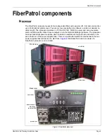
Controller
The FiberPatrol controller (see
) generates the laser light signal that is transmitted into the
fiber sensors. The controller collects the backscatter reflections created by vibrations in the
protected fence, analyzes the signal, and passes the data to the processor.
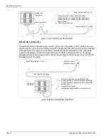
Start module/fiber patch panel
The start module (see
) connects the non-detecting lead cable to the sensor unit in the
equipment room. The start module is housed in a 1 RU fiber patch panel along with a splice tray.
The two sensor fibers from the lead cable must be spliced to two fibers from the start module. Four
additional fibers from the start module are factory spliced to four fiber pigtails, which are attached
to FC/APC connectors on the outside of the of the enclosure. Fiber patch cables then connect the
four fibers to the FiberPatrol controller. The splice tray includes six unused protective sleeves,
which are available to provide access to the dark fibers in the lead/sensor cable. Optionally, a
second splice tray can be added to the enclosure, to make connections to any additional fibers
that are being used. In some configurations, an end module is incorporated into the start module
enclosure inside the rack mounted fiber patch panel. Refer to Chapter 2, Site planning for
additional details.
Outdoor splice enclosure
The outdoor splice enclosure houses all field splices for the FiberPatrol system. The splice
enclosure is also used to protect the FiberPatrol end module when it is installed outdoors. The
splice enclosure is generally mounted on the protected fence.
Figure 3: FiberPatrol start module/splice tray
Figure 4: FiberPatrol outdoor splice components
Rear view
splice tray
start module
open
closed
consumables


