FiberPatrol configurations
Page 14
FiberPatrol Site Planning & Installation Guide
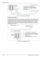
In some instances it is desirable to have a single length of cable running between the equipment
room and the start of the perimeter. This is most common in installations where the sensor unit
equipment is located at a distance from the perimeter. In this case, a dual start/dual end module is
located in the equipment room, and a single lead cable runs to the perimeter fence. Fusion splices
are used to join S1 (blue) in the lead cable to S1 (blue) in the detecting cable. S1 blue runs around
the perimeter and is spliced to S1 (green) in the lead cable going back to the end module in the
equipment room. S2 (orange) in the lead cable is spliced to S2 (orange) in the detecting cable. S2
orange runs around the perimeter and is spliced to S2 (brown) in the lead cable going back to the
end module in the equipment room (see
).
A fully closed perimeter can also be obtained by using a dual start module in the equipment room
and a dual end module located inside a splice enclosure at the start of the perimeter. A single lead
cable runs from the equipment room to the perimeter and S1 and S2 run in opposite directions
around the perimeter with both terminated in the start point splice enclosure (see
).
The partially closed loop configuration uses a dual start/end module in the equipment room and
has two lead cables. This configuration also provides single cut redundancy for a partially closed
perimeter. The two sensing fibers S1 and S2 run in different directions around the perimeter. In the
event of a cut or severely damaged sensor cable, detection will continue around the perimeter in
both directions to the point of the damage.
Open-ended loop configuration
The open-ended loop configuration provides single fiber break redundancy for an open-ended
perimeter. The sensor unit can be located anywhere along the perimeter length with the start and
end points of the detecting sensor cables located at opposite ends. The two sensing fibers S1 and
S2 run in different directions for the length of the cable. Two additional fibers are used to bring the
lead fibers to the opposite ends of the perimeter, where they are spliced to the detecting fibers.
The two detecting fibers run from one end of the perimeter to the other in opposite directions (see
).
Figure 10 FiberPatrol fully closed redundant loop configuration
FiberPatrol sensor cable
fiber optic cable (sensor cable/lead cable)
S1 (sensor fiber 1 - internal to fiber optic cable)
S2 (sensor fiber 2 - internal to fiber optic cable)
fusion splice
splice enclosure
sensor unit
equipment
Note: Cable length = a + b + c + d + e + f + g
dual start/end module
S1 (sensor fiber 1 - spliced return to sensor unit)
S2 (sensor fiber 2 - spliced return to sensor unit)


