Page 6
FiberPatrol Site Planning & Installation Guide
•
outdoor rated splice enclosures for fiber termination and access to fibers
•
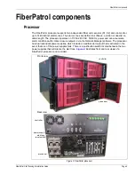
indoor components are rack-mountable in a standard EIA 19 in. equipment rack:
•
processor - locates disturbance, triggers alarms, monitors system status, includes
FiberPatrol system software, configuration software and Network Manager software
•
controller - transmits laser light into two dedicated fibers and receives and isolates back-
scatter signals, analyzes received signal, passes information to processor for analysis
•
start module - 1RU splice tray for connecting non-detecting lead cable to patch cables in
the equipment room, separates the backscatter reflections from the transmitted laser light,
and passes the backscatter to the controller unit
•
LCD keyboard/monitor/mouse combo - 1 RU user interface provides control,
maintenance, calibration and configuration access to the FiberPatrol processor
FP1100X configurations
There are three distinct configurations for the FP1100X series sensor:
•
Loop configurations in which the two sensors run in opposite directions in the fiber optic cable.
•
Split configurations in which the two sensors run in opposite directions, in two fiber optic
cables.
•
Line configurations in which both sensors run in the same direction in the fiber optic cable.
The loop configuration provides single cable cut immunity whereby detection will continue over the
full length of the perimeter in the event of a single cut in the sensor cable. In the split configuration,
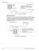
Figure 1: FiberPatrol block diagram - fully closed loop redundant configuration
splice
enclosure
with end
modules
fiber optic sensor cable
non-detecting lead cable
fiber optic
control room
perimeter
controller
start module
fiber optic patch panel
processor
keyboard/monitor/mouse
security
system
management


