background image

Fences

FiberPatrol FP1150 Product Guide

Page 37

The fusion splices in the equipment room and at the end modules are made once the field splices 
have passed the OTDR measurement test.  

Site analysis checklist

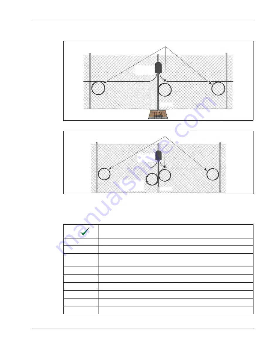
Figure 42 Cable splice service loops and buried isolation loop at fully closed perimeter start/end point

Figure 43 Cable splice service loops and fence-mounted isolation loop at fully closed perimeter start/end point

Description

create a site plan

accurate CAD drawings with precise measurements and/or GPS coordinates

detailed description of fences (type, condition, height, fence rails, climb over 
deterrent hardware, other cables, conduit, or signs attached to fence)

detailed description of gates (type, condition, location, size)

locate all obstacles on site survey

spur fences or fences abutting the perimeter fence 

sidewalks, paths, roads, driveways

buildings, walls and other structures

utilities (sewers, pipes, conduits and electrical cables, etc.)

 service loops (10 m cable length, 60 cm diameter)

splice

enclosure

conduit

buried 13 m 
isolation loop (optional)

 service loops (10 m cable length, 60 cm diameter)

splice

enclosure

conduit

fence-mounted

isolation loop

 (optional)

Summary of Contents for FiberPatrol FP1150 Series

Page 1: ...Guide FiberPatrol Ranging Fiber Optic Fence Protection Sensor FPDA0802 402 Rev B July 15 2020 Product FP1150 Series ...

Page 2: ...ice may not cause harmful interference and 2 this device must accept any interference received including any interference that may cause undesired operation Note This equipment has been tested and found to comply with the limits for a Class A digital device pursuant to part 15 of the FCC Rules These limits are designed to provide reasonable protection against harmful interference when the equipmen...

Page 3: ... 14 Sensor cable non detecting lead cable 14 Cable ties 15 Sensitivity loops fence 16 Service loops 16 Isolation loops fence 16 Buried vault 16 2 Site planning 17 FiberPatrol configurations 17 Loop configurations 17 Split configuration 19 Line configurations 22 Extended lead configuration 23 Site survey 23 Fences 24 Chain link fences 24 Weld mesh fences 24 Fence height considerations 24 Climb over...

Page 4: ...l media 40 Deploying the sensor cable 40 Sensor cable splices 40 Sensor cable terminations 41 Sensor cable bypasses 42 Cable requirements 42 Cable installation for pipeline TPI detection 43 Cable installation for intrusion detection above ground 43 Cable installation for tunneling detection 44 Alarm communication 44 Equipment requirements 44 Dark fibers 44 3 Installing FiberPatrol 45 Installation ...

Page 5: ...neling activity detection 62 Sensor cable verification and test 63 Continuity test 63 OTDR test 63 Control equipment installation 63 FiberPatrol splices 64 4 Maintenance 65 Recommended maintenance 65 System Diagnostics 67 System Status Reporting 67 Remote Systems 67 Local Systems 68 Common Scenarios 68 Troubleshooting procedures 69 Facility and Equipment Access 69 System Inspection 69 Sensor unit ...

Page 6: ...d site feature identification fences 91 At the start point of sensing cable 91 At splice locations 92 At sensitivity loops corners tension posts heavy gauge posts 92 At gate locations 92 At bypass locations 93 At locations of non linear cable deployment 93 At Zone boundary locations 94 Zone boundary and site feature identification buried cable 94 Creating the site map 96 Acquiring the site map ima...

Page 7: ... menu 121 Help menu 121 Alarms Sub Panel 121 Alarm List 121 Alarm Attributes 121 Map Display 121 Clear Alarm button 122 Operator actions 122 Alarm Dialog details 122 Alarm History Sub Panel 123 7 Supervisor s functions 125 Log Sub Panel 125 The Signal sub panel 126 Disturbance signal display graphs 127 Disturbance History display 127 Supervisor menus 127 System menu 128 Manage menu 128 Configure m...

Page 8: ...Page 8 FiberPatrol FP1150 Product Guide Network Manager Alarm reporting Setup 141 Communication content 141 Communication timing 142 ...

Page 9: ...neling activity One FP1150 SU can monitor up to 100 km of buried pipeline or data conduit for TPI To detect people or tunneling activity one FP1150 SU can monitor up to 80 km For fence mounted applications the sensor cable is a communication grade single mode fiber optic cable intended for outdoor installation The cable includes two dedicated sensing fibers Depending on the particular fiber optic ...

Page 10: ... points indoor components are rack mountable in a standard EIA 19 in equipment rack sensor unit 4RU component transmits laser light into two dedicated fibers and receives and isolates back scatter signals via the integral start module analyzes the received signal locates disturbances triggers alarms monitors system status includes Windows operating system FiberPatrol system software configuration ...

Page 11: ...able alarm zone display up to 1440 software defined alarm zones per sensor unit software defined alarm zones enable the redistribution of alarm zones and zone lengths to accommodate future changes in security equipment and requirements fast response time 1 second or less digital recording of alarm history alarm location accuracy typically within 4 m 13 ft increases the overall efficiency of the en...

Page 12: ...the signals to determine the magnitude and location of a disturbance The SU supports two independent fiber optic sensors S1 S2 and can monitor up to 1440 distinct alarm zones The alarm zones are defined in software and do not depend on cable length The SU operates on 100 to 240 VAC 50 60 Hz power and can annunicate alarm conditions with the built in IDS software contact closure outputs or via the ...

Page 13: ...g connections to any additional fibers that are being used at the site A dual end module is included in the fiber patch panel Refer to Chapter 2 Site planning for additional details Outdoor splice enclosure The outdoor splice enclosure houses all field splices for the FiberPatrol system The splice enclosure is also used to protect the FiberPatrol end module when it is installed outdoors The splice...

Page 14: ... fiber optic cable with a medium density polyethylene outer jacket and a waterblock system The non armored loose tube cable is comprised of a 5 unit fiber optic core 12 fiber buffer tubes and PE filler units a central strength member and a rip cord see Figure 6 Sensor cable can be ordered in lengths of up to approximately 12 km 7 5 mi with 12 24 36 or 48 fibers However to facilitate transportation...

Page 15: ...ue orange green brown gray white red black yellow purple rose aqua designation S1 S2 dark dark dark dark dark dark dark dark dark dark blue tube fiber designations 3 mm color coded 12 fiber buffer tubes filler tubes E glass strength rod ripcord MDPE outer jacket S2 orange S1 blue kevlar filler 11 4 mm OD with water blocking gel 9 125 µm with 250 µm coating 3 mm color coded 12 fiber buffer tube fil...

Page 16: ... required for each section of sensor cable at all splice enclosure locations A 10 m service loop is typically comprised of 5 circular loops of cable with a 60 cm 2 ft diameter see Figure 33 For buried applications all field splices are housed in weatherproof enclosures which are protected inside buried vaults Isolation loops fence Isolation loops are optional but are recommended for situations whe...

Page 17: ...g the perimeter length with the start and end points of the detecting sensor cables co located on the protected fence Non detecting lead cable carries the signal from the sensor unit to the start point of the detecting cable The two sensing fibers S1 and S2 run in opposite directions around the perimeter In the event of a cut or severely damaged sensor cable detection will continue around the peri...

Page 18: ...e equipment room In this case there are 2 lead cables between the equipment room and the perimeter Figure 11 FiberPatrol fully closed redundant loop configuration Figure 12 FiberPatrol fully closed redundant loop configuration no field splices FiberPatrol sensor cable fiber optic cable sensor cable lead cable S1 sensor fiber 1 internal to fiber optic cable S2 sensor fiber 2 internal to fiber optic...

Page 19: ...aximum length coverage the sensor unit is located near the mid point Two sensor cables run in opposite directions along the perimeter with each end module located up to 40 km 25 mi away from the sensor unit up to 50 km 31 mi for TPI One sensor fiber provides detection in each direction with S1 running one way and S2 running the opposite way A splice enclosure is required on the fence at the start ...

Page 20: ... being used as a fully closed loop Figure 14 FiberPatrol split configuration 1 lead cable Figure 15 FiberPatrol split configuration 2 lead cables fiber optic cable S1 S2 fusion splice fiber optic termination splice enclosure splice enclosure sensor unit Cable length 2a b c single end module splice enclosure single end module fiber connection module keyboard monitor mouse fiber optic cable S1 S2 fu...

Page 21: ...fiber optic termination sensor unit Cable length 2a b c d e f g splice enclosure dual end module splice enclosure start point of detecting cable end point of detecting cable fiber connection module keyboard monitor mouse fiber optic cable S1 S2 fusion splice fiber optic termination sensor unit Cable length 2a b c d e f g splice enclosure dual end module start point of detecting cable end point of ...

Page 22: ... of the sensor cable Splices may also be required for other site specific features Figure 18 Recommended line configuration Figure 19 line configuration with start point splice fiber optic cable sensor cable lead cable S1 sensor fiber 1 internal to fiber optic cable S2 sensor fiber 2 internal to fiber optic cable fusion splice fiber optic termination splice enclosure sensor unit non detecting lead...

Page 23: ...ayouts sensor cable route non detecting lead cable length length of sensor cable required to cover the perimeter and the location for the electronic components Create a scale drawing of the site e g CAD drawings which indicates the locations of sensor unit equipment fences include type and condition gates include type and size buildings and other structures roads driveways sidewalks paths parking ...

Page 24: ...eld mesh fences A typical weld mesh fence section consists of 3 mm 0 1 in diameter steel wire welded into a grid configuration with horizontal spacing differing from the vertical spacing These fence sections are secured to fence posts and to the adjacent fence panel sections The sections of weld mesh fence are either welded together or connected using clips bolts or rivets The minimum recommended ...

Page 25: ... should be taut and tightly secured at each outrigger The outriggers or extension arms attached to post tops should have a tight press fit set screw or be spot welded Remove or fasten any loose material It is possible to install FiberPatrol sensor cable on barbed wire but extra precautions must be taken to avoid damage to the sensor cable Run the sensor cable along the fence and loop the cable up ...

Page 26: ...e if your application requires that sensor cable be installed on razor ribbon Gates There are generally two types of gates used with fences swinging gates and sliding gates Sliding gates must be bypassed and should be protected by another type of sensor e g a wireless gate sensor or a microwave sensor Swinging gates can be protected by FiberPatrol sensor cable Protected gates should consist of fen...

Page 27: ...e above ground over the gate inside conduit or on the ground under a protective mat Protecting swinging gates with FiberPatrol To cover a swinging gate with FiberPatrol sensor cable a cable management kit p n FPKT0500 is used to protect the sensor cable and allow it to move freely when the gate opens and closes The sensor cable is passed through a section of split conduit that is attached to the f...

Page 28: ...etween the adjacent zones For maximum isolation between zones the isolation loops can be installed in buried vaults see Figure 28 Attach the isolation loops to the fence with cable ties The isolation loops must be far enough away from the gate to prevent the transmission of vibrations into the adjacent zones when the gate is in use The SMS software should be configured to mask alarms from the gate...

Page 29: ...ach side of the gate plus two 13 m 43 ft isolation loops plus length of cable to reach the buried vaults if used Using the cable management kit at the hinged side of protected swinging gates A cable management kit p n FPKT0500 is used at swinging gate locations to protect the sensor cable from being caught or pinched by the gate while allowing the cable to rotate freely when the gate is opening an...

Page 30: ...ty loops at all corner posts terminal posts and tension posts on the fence The sensitivity loops provide additional sensor cable for areas that typically produce lower levels of fence noise The length of cable required for a sensitivity loop can be calculated using this formula 3 X fence height 60 cm 90 cm sensitivity loop cable length requirement For example on a 2 4 m 8 ft fence the service loop...

Page 31: ...A 10 m service loop is typically comprised of 5 loops of cable with a 60 cm 2 ft diameter Service loops should be securely attached to the lower section of the fence beside a fence post Attach service loops directly to the fence fabric using one cable tie at each 45º point of the loop 8 cable ties Figure 31 Sensitivity loop heavy gauge post Figure 32 Sensitivity loop corner post NOTE All double ar...

Page 32: ...solation loop attachment and Figure 28 shows the buried vault installation method for isolation loops Isolation loops are attached to the fence in the same manner as service loops see Figure 33 Transition loops A 30 m 100 ft transition loop is recommended as a buffer between different installation types For example at the transition between fence mounted sensor cable and buried cable A 30 m transi...

Page 33: ...re 36 and Figure 38 Alternatively the building or structure can be protected by attaching sensor cable to it s outside edge with custom P brackets see Protecting masonry walls and buildings on page 30 In this case the sensor cable on the structure should be setup as an independent zone Isolation loops are essential in this application due to the extremely different vibration conducting characteris...

Page 34: ... using conduit For sites that include periods of freezing weather solid wall conduit is required For sites in temperate climates that do not experience freezing weather split conduit can be used Figure 37 Perimeter structure bypass below ground with buried vaults Figure 38 Perimeter structure bypass below ground buried conduit buried isolation loop buried isolation loop buried conduit fence mounte...

Page 35: ...it sections are used the sections must be glued together water tight Use conduit sweeps Do not use 90º elbows Cable bend radius rules must be followed Bury the conduit at least 30 cm 1 ft below ground Figure 39 Split wall conduit Figure 40 Conduit fittings Figure 41 Solid wall conduit split wall conduit split wall conduit couplers split wall conduit sweeps not elbows water tight rain plugs are req...

Page 36: ...specific features such as cable bypasses for gates and other structures on the perimeter The location of splices Sensor cable splices At all designated splice points each section of sensor cable requires a 10 m 33 ft service loop The service loops at splice points allow the sensor cable and splice enclosure to be attached to and removed from the fence fabric for splicing Inside the splice tray sen...

Page 37: ...th precise measurements and or GPS coordinates detailed description of fences type condition height fence rails climb over deterrent hardware other cables conduit or signs attached to fence detailed description of gates type condition location size locate all obstacles on site survey spur fences or fences abutting the perimeter fence sidewalks paths roads driveways buildings walls and other struct...

Page 38: ...or termination splice consumables kit each kit includes the components for 24 splices cable management kit 1 required per swinging gate panel for each protected gate stainless steel cable ties or UV resistant plastic cable ties 1 tie per 50 cm 20 in of cable additional ties required for cable loops and outdoor splice enclosures stainless steel cable ties require an installation tool Note Each FP11...

Page 39: ...ey The survey assesses the site conditions to determine the installation requirements including the area requiring protection alarm zone layouts sensor cable route lead cable length length of sensor cable required and the location for the electronic components Create a drawing e g CAD drawings or a site plan which indicates the length of pipeline or perimeter that requires protection the number an...

Page 40: ...actors must be considered when deploying FiberPatrol sensor cable The length of the section of sensor cable being deployed Clearance and access along the cable route The location of splices and fiber drop points Site specific features such as cable bypasses Sensor cable splices At all designated splice points each section of sensor cable requires a 10 m 33 ft service loop to provide access to the ...

Page 41: ...f two end modules for contiguous FiberPatrol sensors In the example for the contiguous sensors a short length of sensor cable is used to splice the dark fibers that are required from one sensor system to the next Figure 45 Example fiber drop point Figure 46 Single end module installation Figure 47 Back to back end module installation splice enclosure 10 m service loop buried vault ground level HDP...

Page 42: ...s above ground it is strapped to the pipe at 1 to 2 m intervals Figure 49 illustrates the method for above ground sensor cable bypasses Cable requirements Calculating the total length of fiber optic cable is one of the most critical phases of site planning Other equipment requirements including the necessary software activation license are determined by the length of cable Figure 48 Sensor cable b...

Page 43: ...ipeline However for installations where it would be difficult or impractical to install the cable above the pipeline the cable can be installed beside the pipeline For pipelines that have an existing run of fiber optic cable beside them the cable can often be retrofitted for the FiberPatrol sensor Cable installation for intrusion detection above ground The recommended cable installation for above ...

Page 44: ... fibers in the sensor cable for alarm communication applications Equipment requirements The total length of the fiber sensors S1 and S2 in the fiber optic sensor cable sensor cable and lead cable determines the model and number of processors for the FiberPatrol system There are specific FiberPatrol sensor units available for cable lengths up to 5 km FP115005 and up to 40 km FP115040 up to 50 km fo...

Page 45: ...oth ends of the sensor cable 6 Install and connect the sensor unit equipment in the control room 7 Make the fusion splices for the sensor unit and end modules 8 Set up and configure the system software 9 Calibrate the system 10 Test the system to ensure it meets the site s detection requirements Laser light safety Note The FiberPatrol sensor cable is easily attached to the fence However the fusion...

Page 46: ...to 60ºC 22 to 140º F Temperature ratings operation 40 to 70ºC 40 to 158º F Typical outside diameter may vary with cable type 11 2 mm 0 44 in Cable weight may vary with cable type 75 kg km 50 lb 1 000 ft Additional cable requirements central strength member water blocking tape gel filled buffer tubes rip cord WARNING Use care when working with exposed optical fibers The bare fibers are 125 microns ...

Page 47: ...ed to limit cable bending and minimize the angle of cable pay off during unwinding hauling Cable spools must be held firmly in the pay off stands to ensure smooth rotation and prevent any vibration which can damage the drum and the cable Illustrated installation recommendations Attach the sensor cable to the fence fabric with cable ties at the junction of 2 fence wires Space the cable ties 50 cm 2...

Page 48: ...atic is not violated during or after installation Figure 53 Cable tie spacing around corners Figure 54 Static and dynamic bend radius limits 50 cm 20 in secure cable at any changes in direction with a cable tie at each 45º point 11 cm 4 3 in min bend radius smallest allowable bend radius for installed sensor cable 11 cm 4 33 in smallest allowable bend radius when installing sensor cable 22 cm 8 66...

Page 49: ...wer section of the fence using cable ties at each 45º point of the loop Figure 55 Service loops Figure 56 Isolation loops service loops require five 60 cm cable loops 10 m of sensor cable 60 cm 2 ft diameter attach service loops with cable ties at each 45º point around the loop isolation loops require seven 60 cm cable loops 13 m of sensor cable 60 cm 2 ft diameter attach isolation loops with cabl...

Page 50: ... minimum hole size For instances where the cable must be unreeled and pulled back to accommodate site specific installation requirements e g service loops gates bypasses lay the cable on the ground in a large figure 8 pattern to prevent twisting or kinking Never lay the cable in a circular roll Note Conduct the OTDR cable testing BEFORE filling the vault with sand Note The conduit must be sloped a...

Page 51: ... dispensed if the cable is being deployed from a trailer or truck it will have to be pulled back to pass through the conduit a sufficient amount of cable must be pulled back for isolation loops service loops and gate coverage as required FiberPatrol installation 1 Ensure that there is enough sensor cable in the equipment room to reach the fiber connection module in the equipment rack and to make a...

Page 52: ... to the fence fabric Attach the cable to the fence fabric at the junction of two fence wires The recommended spacing between cable ties is 50 cm 20 in Attach the sensor cable at both sides of each fence post approximately 25 cm 10 in away from the post 1 Beginning at the start point post attach the sensor cable to the fence at the junction of two fence wires at the specified height above ground po...

Page 53: ...rk the positions of any hardware on the fence post that will require notches in the conduit 4 Make any required notches in the conduit 5 Place the notched half of the conduit under the cable against the fence post and hold it in place 6 Press fit the sensor cable into the split loom so the split loom extends 7 5 cm 3 in beyond the top and bottom of the split conduit 7 Fit the other half of the con...

Page 54: ... designed to be anchored with a single screw Self tapping 3 16 in by 1 1 4 in concrete screws such as Tapcon screws with slotted hex washer heads are recommended The required mounting holes are 5 32 in diameter and 1 1 2 in deep and are centered 1 5 in from the edge of the surface The cable loop in the P clamp is vinyl coated and sized to grip a standard sensor cable snugly once the clamp is close...

Page 55: ...rding to the site plan 3 Make any required field splices excluding the end module and start module splices 4 Use an OTDR to measure the loss in each spliced fiber from both ends of the sensor cable before making the splices to the end module and start module 5 Install and connect the control room equipment 6 Make the fusion splices for the sensor unit and end module 7 Set up and configure the syst...

Page 56: ...of the two readings average loss over the full length of installed cable must be 0 25 dB km 0 4 dB mi or less for up to 80 km of sensor cable average loss over the full length of installed cable must be 0 24 dB km 0 39 dB mi or less for up to 100 km of sensor cable TPI maximum individual event loss limit 0 1 dB Cable handling recommendations Bend management systems must be used to restrict cable b...

Page 57: ...tom of the trench will also provide good detection for digging from above The maximum length for third party interference is 50 km side 100 km total Intrusion detection vehicles and human targets For intrusion detection the recommended installation places the fiber optic sensor cable 15 to 70 cm 6 to 28 in below the ground s surface For loose soil types that do not conduct vibrations well like san...

Page 58: ...detection the recommended burial depth for the sensor cable is from 15 to 70 cm 6 to 28 in see Figure 65 burial depth tunneling activity the recommended burial depth for the sensor cable is a minimum 2 m 6 5 ft see Figure 66 recommended clearance minimum 6 m 20 ft of clearance on each side of the sensor cable to prevent vibrations created by an object from disturbing the cable total clear area cen...

Page 59: ...uality fusion splices the fusion splices are contained inside splice trays Note Vegetation within the 12 m 40 ft clearance area should be kept below a height of 30 cm 12 in Figure 67 Minimum separation distances from obstacles Figure 68 Smallest allowable bend radius sensor cable 6 m 20 ft 6 m 20 ft sensor cable min clear area min clear area NOTE ground surface 2 m 6 6 ft typical The clear area mu...

Page 60: ...m 30 in wide X 107 cm 42 in long gravel layer to depth of cable entry points 13 cm 5 in nominal plus 5 cm 2 in gravel layer on the bottom of the pit sand layer pour sand over cable splice enclosure and gravel layer to completely fill the vault cable entry points drill holes for cable entry 2 cm 0 8 in recommended hole size Figure 69 Ground level buried vault closed and open Figure 70 Buried vault ...

Page 61: ...d to the back of the equipment rack FiberPatrol cable installation pipeline TPI 1 Ensure that there is enough sensor cable at the head end location to reach the fiber connection module in the equipment rack and to create a 10 m service loop inside the equipment room 2 Backfill the trench over the pipeline to a level depth of 30 cm 1 ft above the pipe 3 Run the sensor 1 sensor cable to the designat...

Page 62: ...able and repeat the installation procedure for the sensor 2 cable in the opposite direction along the perimeter FiberPatrol cable installation tunneling activity detection 1 Ensure that there is enough sensor cable at the head end location to reach the fiber connection module in the equipment rack and to create a 10 m service loop inside the equipment room 2 Dig the trench along the designated cab...

Page 63: ...d to be installed in an EIA 19 in equipment rack The rack requires a mounting depth of 20 in 51 cm plus a minimum 2 in 5 cm of front space between the equipment and the rack doors and at least 6 in 15 cm of rear space for cables and ventilation The overall depth of the rack must be a minimum of 28 in 71 cm Both the front and back of the equipment rack must be accessible for a technician to make th...

Page 64: ...e protective dust caps on the connectors Leave the dust caps in place until you make the connections Do not touch the ends of the fiber connectors or allow the ends of the fiber connectors to touch anything To make the connection remove the dust cap thoroughly clean the connector ends and then gently insert the FC APC connector and tighten until finger tight Note The loss at splices must not cause...

Page 65: ... any loose pieces gates ensure that all gate hardware is tight and secure and cannot move in the wind there are no washouts or depressions under the fence vegetation beside and above the fence is cut back and cannot make contact with the fence the frequency at which vegetation must be cut back depends on the local growing conditions the sensor cable is fastened firmly against the fence fabric and ...

Page 66: ... to potential damage Check the LEDs on the RAID hard drives blue Led lit ON Verify that there is adequate clearance for ventilation and clean the processor s filters if required clean the filters in warm water and ensure that they are completely dry before replacing them in the filter trays on the front doors 5 If a reflection is found at the start of the sensor cable you must clean both the exter...

Page 67: ...ble cut Warning non critical failure intrusion detection still possible Disarmed critical failure that disables the system no detection Head End alarms are generated and reported when the general system status changes to Disarmed Head End alarms are treated by the FiberPatrol system the same way intrusion alarms are By default they are reported with a location of 1000 and zone label HeadEnd and ar...

Page 68: ...A properly configured uninterruptable power supply UPS is recommended for use with FiberPatrol head end equipment Soft shutdown and remote reboot functionalities are also strongly recommended Sensor unit crashes are rare occurrences for properly installed and configured equipment Often they are caused by external factors such as elevated operating temperature unstable line power or improper handli...

Page 69: ...steps in addressing a system malfunction are System inspection Connections check Sensor unit reboot Documentation and reporting Facility and Equipment Access Obtain the necessary permissions and means keys codes etc to access the facility the equipment room and the equipment cabinet System Inspection Note the general conditions in the equipment room and rack enclosure including Ambient temperature...

Page 70: ...y connected Cables have no visible damage The connector keys are aligned if not aligned a connector will protrude more than the others For both fiber optic connections verify that the connector is not loose or over tightened the FC APC connectors should be finger tightened until snug The fiber optic cables are connected according to the labels Fiber optic cables are routed loosely without excessiv...

Page 71: ...g the report include the following information How the problem was discovered The immediate indications of the problem The steps taken to diagnose and solve the problem The results of the remedial actions Any observation made while following the system check procedures The final state of the system Any other notes concerning the problem The name company and contact information of the person provid...

Page 72: ...Troubleshooting procedures Page 72 FiberPatrol FP1150 Product Guide ...

Page 73: ...e sensor unit and will restart the FiberPatrol IDS software when it detects that the program is not running User access to the SU is via the keyboard monitor mouse unit in the equipment rack When the sensor unit starts the Launch FiberPatrol popup displays and counts down while the FiberPatrol IDS software initializes To stop the initialization process and prevent the FiberPatrol IDS software from...

Page 74: ...re is disabled The FiberPatrol software and software license are factory installed and the FiberPatrol software will auto start when the sensor unit is powered up Once the FiberPatrol software is running it will restart automatically if it is shut down by the user When FiberPatrol is starting a window displays the time remaining until the software is launched CAUTION The FP1150 configuration setti...

Page 75: ...tart mode during the initialization process Safe start mode prevents potential damage to the photo detectors that can be caused by incorrect fiber installation If safe start detects a fiber problem the user must login at the Installer level to continue the initialization process Figure 75 FiberPatrol login window Figure 76 FiberPatrol System Status panel during initial startup Figure 77 FiberPatro...

Page 76: ...onnection After logging in as the Installer the user will be prompted to disconnect one of the sensor cables from the processor if a cross connection is suspected 2 Disconnect 1 of the 2 sensor fibers from the processor 3 The Installer level user can select Skip Check to initialize in safe mode to prevent possible damage Figure 78 FiberPatrol Safe Start Warning Figure 79 Disconnect sensor ...

Page 77: ...es the FP1150 software will determine if there is a cross fiber connection 5 If no problems are detected with the sensor cable installation a Safe Start Check complete message will display At this time the installer should select Skip SafeStart in the future Figure 80 Safe Mode warning Figure 81 Cross fiber detected Figure 82 SafeStart Check Complete ...

Page 78: ... installation details For Loop configurations Sensor 1 and Sensor 2 run in opposite directions around the perimeter and back to the start point see Figure 84 There are two types of Loop configurations Figure 83 FiberPatrol default Alarm screen installer access level Figure 84 FiberPatrol sensor cable configurations Alarm processing buttons Menu selection bar Sub panel tabs Perimeter map display Al...

Page 79: ... Auto Gain process is complete before proceeding with step 3 3 Once the Net Signal has stabilized between the 2 yellow lines select the Auto Set button The Auto Set process may take several minutes to complete While the Auto Set process is running the System Status will indicate Initializing The Auto Set process will match the Set Start and Set End with the Actual Start and Actual End for each sen...

Page 80: ...the maximum lengths of S1 and S2 Global Setup The Global Setup button on the System tab opens a dialog that simplifies the initial setup of the FP1150 sensor 1 Enter the maximum lengths of S1 and S2 2 Select the installation Medium e g Flexible Fence Chain Link 3 Once the lengths and Medium are specified the system will automatically set the Pulse Rate Frame Rate Low Frequency High Frequency Syste...

Page 81: ...nit and then walks around the perimeter or along the pipeline causing alarms at the locations of the site s features As the tests are conducted the person must carefully note the time and location of each test Once the tests are completed the tester returns to the FiberPatrol SU reviews the results of the tests in the Alarm and Event Logs and records the appropriate details for future use in the M...

Page 82: ... amount of force consistent Conduct a series of three tap tests at the location of each feature or zone boundary waiting at least 15 seconds between tests Calculate the average location from the three tests at each point and use the average to set the location of the feature in the system software Use the table in Appendix C to record the test results Note Refer to Supervisor s functions on page 1...

Page 83: ...e and the Event Life to 10 seconds 2 Select Configure Alarm Auto Clearing and check the Automatically Clear Alarms and Upon Completion checkboxes Set the time to 10 seconds and apply the changes see Figure 88 Note By convention Sensor 1 from the sensor unit or from location 0 goes in the direction of increasing zone numbers i e Sensor 1 starts and runs to zone 1 then zone 2 then zone 3 etc Note If...

Page 84: ... loop e g average location of 3 tap tests for Sensor 1 134 m subtract 10 m to get back to the start point of Sensor 1 134 m 10 m 124 m subtract 10 m for the splice point service loop 124 m 10 m 114 m in this example see Figure 89 there is an isolation loop subtract 10 m for the isolation loop 114 m 10 m 104 m the Set Start for Sensor 1 104 m Figure 88 Temporary settings for location calibration No...

Page 85: ...guration select the Configure menu Save Configuration Calibrating the Set Start for Sensor 2 and Set End for Sensor 1 Loop configurations Adjust the Detection Settings see Test setup on page 83 1 Verify the Sensor 1 Offset 0 Sensor 1 Scale 1 Sensor 2 Offset 0 Sensor 2 Scale 1 2 Proceed to a point that is 10 m 33 ft away from the sensor start point on the Sensor 2 side and conduct 3 tap tests at th...

Page 86: ... Sensor 1 high value 10 m End point of sensing for Sensor 1 Add 10 m for the start point service loop If there is an optional isolation loop add 10 m to put the end point inside the isolation loop 8 Set the value for Set End for Sensor 1 to the above result e g average location of 3 tap tests for Sensor 1 2738 m add 10 m to get to the end point of Sensor 1 2738 m 10 m 2748 m add 10 m for the start...

Page 87: ...to the Sensor 1 Set End value 3 Set the System End to Sensor 1 Set End value Sensor 2 Set End value 4 Save the configuration Select the Configure menu Save Configuration Verify the sensor start point 1 Conduct a series of 3 tests to create 3 alarms at location 0 Location 0 is at the S1 end module and represents the start point of detecting cable 2 Verify that the alarm results are not negative mus...

Page 88: ...perimeter to the sensor unit This should also be the start point of the detecting sensor cable for Sensor 2 The tests at this location may cause alarms on both Sensor 1 and Sensor 2 4 Conduct as many tests as required between the perimeter and the sensor unit to identify the lead cable for Sensor 1 and Sensor 2 5 Return to the perimeter beginning of Sensor 2 detecting cable and continue this proce...

Page 89: ...the end point of the sensing cable and conduct a series of 3 tests at this location waiting at least 15 seconds between tests 2 Take an average location from the 3 tests and add 10 m to the average location 3 Add 10 m for the splice point service loop 4 Enter the result in the Set End boxes for Sensor 1 and Sensor 2 e g average location of 3 tap tests 1462 m add 10 m to get to the end point add 10...

Page 90: ...rly identifies each feature and zone boundary that must be located for the map display 1 Make a copy of the Location calibration table from Appendix c see Figure 96 for an example of the Location calibration table for fence mounted 2 Conduct a series of 3 tests at each site feature and Zone boundary location waiting at least 15 seconds between tests Note the time of each test on the Location calib...

Page 91: ...ses gates buildings structures and other obstacles that are located on the perimeter At the start point of sensing cable At the start point of the sensing cable tap the cable 10 m away from the start point post and subtract 20 m to confirm the start point location Note The FiberPatrol system uses soft zone boundaries which are defined in software The location resolution of FiberPatrol is 4 m 13 ft...

Page 92: ... the distance back to the isolation loop and 10 m to place the zone boundary inside the isolation loop Tap the cable one fence panel away from the gate location if there are no service loops or isolation loops and the gate will be included as part of another zone Figure 99 Tap test location outdoor splices Figure 100 Tap test location at corners or heavy gauge posts Figure 101 Tap test location ga...

Page 93: ...d end locations At locations of non linear cable deployment Tap the cable at the fence posts adjacent to the non linear deployment Figure 103 Tap test location gate part of zone Figure 104 Tap test location bypassed obstacles Figure 105 Tap test location non linear cable deployment tap cable 1 panel away from service loop loop service loop service tap cable 1 panel away from service loop tap cable...

Page 94: ...ix c as are required to calibrate physically test each feature and zone boundary Each designated soft zone boundary and feature should be marked on the ground above the sensor cable Photos or drawings of the zone boundaries and feature locations should be provided for the tester In addition the tester should record the GPS coordinates of the zone boundaries and features on the Calibration spreadsh...

Page 95: ...ensor cable for Sensor 1 i e at the point where the lead cable runs from the perimeter to the sensor unit This should also be the start point of the detecting sensor cable for Sensor 2 The tamp tests at this location should cause alarms on both Sensor 1 and Sensor 2 4 Conduct as many tamp tests as required between the perimeter and the sensor unit location to identify the lead cable for Sensor 1 a...

Page 96: ... Acquiring the site map image Map image navigation Use the mouse wheel to zoom in and out Double left click to zoom in Double right click to zoom out Left click hold and drag to pan across the image Right click hold and drag to rotate the image 1 Start the IDS Map Manager application Figure 109 shows the Map Manager start screen Figure 110 shows the map creation tools and Figure 111 shows the map ...

Page 97: ...Go to Location Figure 110 Map creation tools Figure 111 Map editing toolbar Figure 112 New Project dialog Hover the mouse cursor over a toolbar item or menu item and a description of the function will display menu bar tool bar menus Undo Redo Removes selected item from map Select Area of Interest Measure the ground distance Set map orientation to North Up Go To Location Extract an Area of Interest...

Page 98: ...a device select Project New Device Enter the IP address of the FiberPatrol sensor unit if you don t know the sensor unit s IP address enter 127 0 0 1 Enter 4122 as the Port number Figure 113 Go to Location dialog Note If the selected zoom level is too high there will not be an image available see Figure 114 Reduce the zoom until an image displays Note Save the project frequently to prevent data lo...

Page 99: ...s will be displayed is created in IDS Map Manager In order to accurately display the locations of alarms you place vertices on the perimeter line and define the locations of the vertices in the IDS Map Manager software 1 Select and highlight the Sensor in the Project tree Select the Perimeter Editor tool and then select the Perimeter Extender tool The Zoom level should fully display the site s pro...

Page 100: ...Left click and drag this vertex to the desired location To change the location of a vertex left click and release to select the vertex then left click and hold to drag the vertex to the desired location Figure 117 Drawing the perimeter Note To end the drawing sequence select Ctrl 3 The perimeter line ends at the last vertex Note Once the perimeter is drawn a table is created based on the physical ...

Page 101: ...t the AOI tool Select the AOI by left clicking the upper left corner then moving the cursor diagonally across the map and left clicking the bottom right corner Keep the AOI aspect ratio as close to 5 2 and as centered as possible 3 Select the Extract AOI button Note To use the alarm zones as created in the IDS Map Manager proceed to Select the Area of Interest AOI on page 101 Figure 119 Selecting ...

Page 102: ... 10 Save the Project and close IDS Map Manager Importing Configuration Files into the FiberPatrol IDS software 1 Save the three configuration files that were exported from IDS Map Manager to removable media 2 On the FiberPatrol sensor unit navigate to C FiberPatrol Configuration Rename the existing files by adding ORIG to the end of the file name before the extension e g IDS map calibration ORIG t...

Page 103: ...e Site ID and Unit ID to the appropriate numbers Verify that there are no License Errors 6 Save the Configuration Figure 122 Verifying the Map image Figure 123 About FiberPatrol dialog The map image and perimeter line created in IDS Map Manager display when the new configuration files are loaded Enter the appropriate details ...

Page 104: ...e and the zone name is New Zone All zones must be assigned unique Zone Labels and Zone Names including disabled zones Note The end location of one Zone boundary must be the same as the start location for the next Zone boundary i e if Zone 1 ends at 100 m then Zone 2 begins at 100 m For a fully closed perimeter the end point location of the final Zone must be the same as the start point location fo...

Page 105: ...rough the remote interface When selected the FiberPatrol IDS transmits data packets at regular intervals leave enabled Interface Mode is a drop down menu that selects the remote interface type from the available options The following are two of the standard options In TCP IP Server mode the FiberPatrol IDS implements a TCP IP server It accepts a single connection through the default Port 4122 Note...

Page 106: ...e computer s IP address or the DNS name The Communication Monitor field is used to monitor the incoming remote interface messages for the selected connection Setting Alarm Detection Parameters The Alarm Detection Parameters are available on the Signal sub panel The Frame Duration defines the time period in which new disturbance events are created Shorter Frame Durations are used for flexible fence...

Page 107: ...ontinuing reverberations caused by the initial disturbance The default value is 0 3 seconds The Disturbance Range defines the length of cable over which a current disturbance event can be added to by additional disturbances in the same general area The default value is 12 m 39 ft The Event Life is the length of time in seconds following an event alarm before another event alarm can be declared at ...

Page 108: ...eatedly strike a 1 2 in steel plate that is placed on the ground directly above the sensor cable Setting the full cable Sensitivity Thresholds The full cable Sensitivity Thresholds are software settings that control the sensitivity of the entire sensor When correctly set the full cable Sensitivity Thresholds make the FP1150 sensor sensitive enough to detect an intruder while keeping nuisance alarm...

Page 109: ...ettings for Zone 1 require adjustment proceed to step 3 3 To adjust the Sensitivity settings for an individual zone open the Manage menu and select Zone Definition see Figure 124 4 To adjust the sensitivity thresholds for an individual zone change the threshold value from the default value of 1 to the desired value 5 Perform a series of intrusion tests to verify the new settings Note Adjusting the...

Page 110: ...factors like strong wind and heavy precipitation that can cause nuisance alarms Environment Compensation is accessed through the Service menu There are two different modes of Environment Compensation Spatial and Temporal Set Temporal Environment Compensation first Temporal Compensation Temporal Environment Compensation works at a localized point of the sensor and removes background signals based o...

Page 111: ...gnal from the immediate locations on both sides which are defined by the Exclude Length setting Enabled 1 yes 0 No Spatial Environment Compensation is applied to the cable section if a value of 1 is entered in this column A value of 0 disables Spatial Environment Compensation in the cable section Start and End Locations The length of a section is defined by entering a start location and an end loc...

Page 112: ...o the sensor cable typically generates a number of disturbances in a specific pattern at different locations and times These disturbance events are considered to be a cluster belonging to the same parallel motion event if the period between consecutive disturbances is less than the Disturbance Time setting The unit for Disturbance Time is seconds Disturbance Life Disturbance Life sets the time lim...

Page 113: ...ignals above this threshold setting are analyzed to determine a valid perpendicular motion event Disturbance Time An object moving perpendicular to the sensor cable typically generates a number of disturbances for a limited time depending on the speed and length of the moving object as well as other factors related to the fence The Disturbance Time is the period in seconds in which a moving object...

Page 114: ...to Senstar technical support for analysis When enabled the Save Raw Data function saves the configuration folder and creates a sub folder every 5 minutes Load Raw Data An advanced user can use the Load Raw Data function to help fine tune an FP1150 sensor Use the Load Raw Data function to replay the saved data from detection tests Make small adjustments to the detection parameters while replaying t...

Page 115: ... of the end see Figure 133 The Refresh button resets the net signal calculation used for the net signal status checkpoint and the net signal graph on the system tab The Global Setup button is used during the initial configuration to specify the maximum length of each sensor and the type of installation medium Once the correct medium is selected a number of default parameters are updated accordingl...

Page 116: ... media so the configuration data can be reloaded in the event of a catastrophic system failure Figure 133 Additional settings Use the signal graph to verify the health of the system in Linear mode or by dB The Global Setup can be used to simplify sensor calibration by specifying the The Refresh button resets the system s net signal calculation The Troubleshooting button displays the Troubleshootin...

Page 117: ...An alarm is a notification of an event either in progress or complete An alarm is generated for each event once the event is declared one event one alarm Time of Alarm The date and time the alarm was generated The alarm time may differ from the time the disturbance began Current Alarms An alarm remains current and is reported until the alarm is acknowledged or the system is disarmed The event may ...

Page 118: ...h FiberPatrol exe The default location of the FiberPatrol software is C FiberPatrol FiberPatrol exe Enter your user name and password select your access level and then select OK Once you have entered a valid password for the selected access level the FiberPatrol software will proceed with the initialization sequence If an incorrect password was entered or the Cancel button was selected the program...

Page 119: ...FiberPatrol Software Interface It displays detailed attributes of current alarms and enables the Operator to process alarms via the Clear Alarm button The menu bar at the top of the panel provides access to some functions Menu items that are not available to the Operator access level are grayed out Status Panel The Status Panel at the bottom of the Window contains three fields that are common to a...

Page 120: ... is severely compromised and the intrusion detection capability is lost Alarm Status field The Alarm Status field displays the current number of alarms No Alarms steady There are no current alarms Alarm 2 of 2 steady There are 2 current alarms and the second alarm is selected Alarm 1 of 3 flashing There are 3 current alarms at least one of which is in progress and the first alarm is selected Alarm...

Page 121: ... are removed from the list according to the system s Alarm Auto Clearing settings Alarms can be selected from the alarm list by selecting the corresponding line on the list The selected alarm is highlighted and its location is displayed on the Map and in the Status Panel Location field To clear the currently selected alarm select the Clear Alarm button or double click the highlighted line in the A...

Page 122: ...ialog details The Alarm Dialog includes The alarm details contained in the Alarm List An Established Cause field used by the Operator to enter a description of the cause of the alarm A field used by the Operator to describe the actions taken A Clear Alarm button to clear the alarm Once cleared the alarm is removed from the Current Alarms list Cleared alarms are accessible through the Log sub panel...

Page 123: ... All events are shown regardless of whether the corresponding alarms have been cleared The events in progress are shown as red dots the completed events are shown as yellow dots and current disturbances not yet events are shown as gray dots The horizontal axis of the display graph is the location and the vertical axis is the time The Alarm History sub panel is provided for information purposes the...

Page 124: ...Page 124 FiberPatrol FP1150 Product Guide ...

Page 125: ...arm entries are added at the top of the list as they occur These entries are copied from the Alarm List on the Alarms sub panel The Event Log list contains information on system events including logins system initialization reports hardware performance notifications alarm clearing activity and operator text entries The Event Log list also includes the System Checkpoints details pass or fail The al...

Page 126: ...l sub panel The Signal sub panel displays the detection parameter settings and includes three Data Displays that provide a graphical representation of the detected disturbances based on time or location Disturbance Count The system supervisor can adjust the settings and view the results on the signal display graphs Figure 144 shows the FP1150 Signal sub panel Figure 142 Log sub panel Figure 143 Ev...

Page 127: ...on range A disturbance that is not yet associated with an event is indicated by gray bars When an alarm is generated the corresponding disturbance bars change to red The Detection Thresholds and Detection Window parameters set the conditions for alarm generation Unassigned gray disturbance bars are discarded at the end of the Disturbance Life time setting Event red disturbance bars are discarded o...

Page 128: ...nage Change Password see Password maintenance on page 132 Manage Test Alarm The Test Alarm function is used to simulate an alarm This function generates a simulated alarm at a random location and is generally used for demonstration personnel training and functionality verification Configure menu Configure Save Configuration Saves the current system settings into the configuration file Configure Lo...

Page 129: ...f various system failures for demonstration personnel training and functionality verification The Status dialog includes a Raid Alerts button to check the status of the Raid hard drives 1 Select Service Status 2 Select the Raid Alerts button on the Status dialog 3 Verify that there are no Raid Alerts Service Frequency Display see Frequency Display on page 115 Service Environment Compensation see E...

Page 130: ...ation range to a zone The Zone Label and Zone Name are text strings which identify the zone The Zone Label cannot include any spaces Each zone requires a unique Zone Label and Zone Name In the Zone Type column the first digit identifies the sensor type 1 fence mount 6 buried cable The second digit indicates if the zone is currently active 1 or masked 0 Zone Type does not apply to the Head End zone...

Page 131: ...etting applies to the zone These settings do not apply to the Head End zone The Display Mode parameter controls the visual annunciation of the alarms for a zone including the appearance of the alarms on the site map and the information shown in the Event Location indicator The following table includes the Display Mode values and their meanings a value of 1 indicates that the global setting applies...

Page 132: ...essfully Alarm Auto Clearing This dialog enables the Supervisor to setup the Alarm Auto Clearing function Select Configure Alarm Auto Clearing to setup automatic alarm clearing no operator action required The default setting is for alarms to be cleared automatically after a 24 hour period The length of time can be changed and alarms can be auto cleared when they are completed The Allow Active Alar...

Page 133: ...k the Upon Completion checkbox for alarms to clear automatically when completed 4 Apply the changes Remote Interface Select Configure Remote Interface to display the Remote Communications Interface dialog This dialog provides access to the Remote Interface Controls Figure 151 FiberPatrol Alarm Auto Clearing Settings Figure 152 FiberPatrol Remote Communication Interface Settings ...

Page 134: ...Page 134 FiberPatrol FP1150 Product Guide ...

Page 135: ...excess of 500 m needs to be added to the licensed section Each meter licensed activates both sensor channels rack mount keyboard monitor mouse combo GB0296 15 rack mount 15 in LCD monitor with keyboard and mouse for maintenance access to FiberPatrol processor rack mount keyboard monitor mouse combo GB0296 19 rack mount 19 in LCD monitor with keyboard and mouse for maintenance access to FiberPatrol...

Page 136: ... steel GH1080 14 bag of 100 stainless steel cable ties 26 cm 14 in requires installation tool cable ties stainless steel GH1080 14C bag of 100 coated stainless steel cable ties 26 cm 14 in requires installation tool cable ties stainless steel GH1080 20 bag of 100 stainless steel cable ties 51 cm 20 in requires installation tool cable ties stainless steel GH1080 20C bag of 100 coated stainless stee...

Page 137: ...alarms within 45 m may be reported as one alarm simultaneous alarms separated by more than 45 m will be reported as individual alarms location accuracy 4 m 13 ft in a quiet environment Virtual alarm zones 1440 distinct software defined alarm zones per sensor unit Cable cut reported and located to within 30 m 98 ft FiberPatrol sensor cable Sensor cable part number standard cable FPSP04XX XX no of f...

Page 138: ...3 s Disturbance Range defines the length of cable over which a current disturbance event can be added to by additional disturbances in the same general area default 6 m Event Life the length of time in seconds after which an event is complete provided that no additional disturbance has occurred within the localized area of the event default 60 s Environment Compensation used to help screen out env...

Page 139: ...FiberPatrol FP1150 Product Guide Page 139 c Location calibration table tap point description time location 1 time location 2 time location 3 avg location ...

Page 140: ...Page 140 FiberPatrol FP1150 Product Guide test point description GPS coordinates time location 1 time location 2 time location 3 avg location ...

Page 141: ...tion Device identification site ID internal unit ID internal description optional System information time stamp system operational status Pre alarm condition optional Alarm information alarm ID internal time tamp location sensor location GPS and or zone event parameters type magnitude duration etc Alarm clearing notifications acknowledgements The FiberPatrol remote communication interface accepts ...

Page 142: ...de Communication timing By default FiberPatrol alarm reports are transmitted approximately once per second When a new alarm is generated a report with the new alarm information is transmitted immediately Alarm information is transmitted for as long as an alarm is active typically for the duration of an event plus 60 seconds The reporting interval is adjustable Continuous reporting can be disabled ...

Reviews: