Calibration setup
FiberPatrol FP1150 Product Guide
Page 89
3.
Take an average location from the 3 tests, and subtract 10 m from the average location.
4.
If there is a splice point service loop at the start of the sensing cable, subtract the 10 m loop.
5.
If there is an optional isolation loop at the start of the sensing cable, subtract another 10 m
from the result (to place the start point inside the isolation loop).
6.
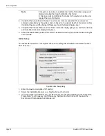
Enter the result in the Set Start box for both Sensor 1 and Sensor 2 (they will nominally have
the same values for Set Start).
•
e.g., average location of 3 tests = 86 m
subtract 10 m to get back to the start point
(86 m - 10 m = 76 m)
subtract 10 m for the service loop
(76 m - 10 m = 66 m)
if there is an optional isolation loop, subtract 10 m
(66 m - 10 m = 56 m
the Set Start for Sensor 1 and Sensor 2 is 56 m
7.
Save the configuration (Select the Configure menu > Save Configuration).
Calibrating the Set End position (Line configurations)
1.
Proceed to a location that is 10 m (33 ft.) before the end point of the sensing cable and
conduct a series of 3 tests at this location, waiting at least 15 seconds between tests.
2.
Take an average location from the 3 tests, and add 10 m to the average location.
3.
Add 10 m for the splice point service loop.
4.
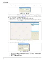
Enter the result in the Set End boxes for Sensor 1 and Sensor 2.
•
e.g., average location of 3 tap tests = 1462 m
add 10 m to get to the end point
add 10 m for the splice point service loop
(1462 m + 10 m + 10 m = 1482 m)
the Set End for Sensor 1 and Sensor 2 = 1482 m)
5.
Save the configuration (Select the Configure menu > Save Configuration).
6.
Proceed to the end point of the sensing cable and conduct a series of tap tests to verify the
setting.
Calibrating the Offsets and Scales (Line configurations)
1.
Verify the Sensor 1 Offset = 0, Sensor 1 Scale = 1, Sensor 2 Offset = 0, Sensor 2 Scale = 1.
2.
Save the configuration (Select the Configure menu > Save Configuration).
Note
The location for Sensor 1 and Sensor 2 will nominally be the same.
Note
The end of the FiberPatrol sensing cable must be defined. The Set End
values for Sensor 1 and Sensor 2 define the end location of the sensor.
Note
The location for Sensor 1 and Sensor 2 will nominally be the same.


