Setting Alarm Detection Parameters
FiberPatrol FP1150 Product Guide
Page 115
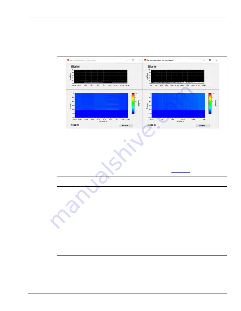
Frequency Display
The FiberPatrol FP1150 Series sensor includes a Frequency Display window for each sensor,
under the Service menu. In Zone Mode, the Frequency Display window enables an advanced user
to view signal amplitudes on a zone by zone basis. In Location Mode, you can specify a location
and view the signal amplitudes at that location.
Additional installer level settings
The Installer access level can verify the health of the system by viewing the Signal graph in linear
mode and dB mode. Linear mode shows the COTDR signal from the cable and dB mode shows
the approximate loss in the cable and the location of the end (see
).
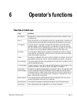
The Refresh button resets the net signal calculation (used for the net signal status checkpoint and
the net signal graph on the system tab).
The Global Setup button is used during the initial configuration to specify the maximum length of
each sensor and the type of installation medium. Once the correct medium is selected a number of
default parameters are updated accordingly, including Environmental Compensation.
The Troubleshooting button can be used to disable the SafeStart feature once the sensor
connections are verified. It also enables an advanced user to troubleshoot the system by checking
the status of the hardware components of the SU.
Figure 132 Frequency Display screens (S1 & S2)
Note
Do not use the Signal graph in place of the OTDR scanning during the
system installation.
Note
DO NOT adjust the Troubleshooting Settings without direct technical
support.


