FP400 Product Guide
Page 15
2
Site planning
FP400 configurations
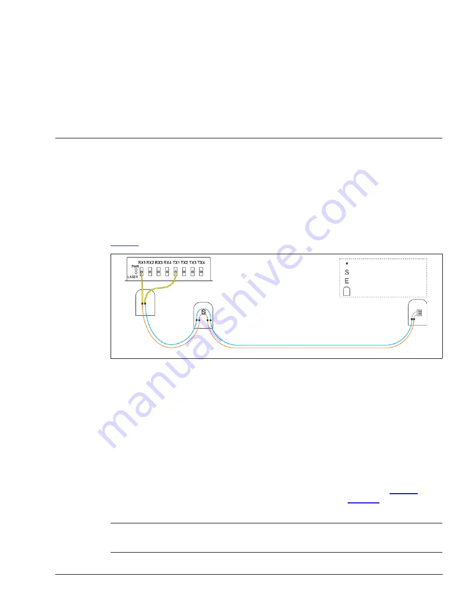
The recommended method for installing the sensor cable is to use the minimum number of splices
possible for each sensor zone. This includes 2 splices for the lead-in cable connections to the
processor, 4 splices for the start module, and 2 splices for the end module. Midspan access
techniques are recommended for non-spliced (expressed) fibers passing through an enclosure.
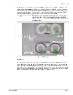
illustrates an FP400 sensor zone with the minimum 8 fusion splices.
The FP400 detection zone runs between the start module and end module, and can include up to
300 m of sensor cable. For planning purposes approximately 15% extra cable should be budgeted
for splice point service loops and installation variations. The 15% overage allows one sensor zone
to protect approximately 255 m (840 ft.) of perimeter fence. For longer perimeters, the 4 zones can
be installed back to back thereby extending coverage to a maximum length of 1.2 km (0.75 mi.) of
sensor cable. Four contiguous zones of sensor cable can cover approximately 1 km (0.62 mi.) of
fence. The coverage length can be extended indefinitely by networking multiple FP400 sensors
back to back.
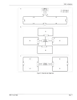
Some FP400 zone configurations require only 2 dedicated fibers. For those configurations there is
no need to express the 10 unused fibers through the enclosure. In this situation, it is acceptable to
cut the sensor cable and splice only the required fibers. In the example drawings in
b require expressed fibers but c does not. In the example drawings in
, a requires
expressed fibers but b and c do not.
Figure 8 Single zone linear configuration (minimum splices)
Note
Expressing fibers through splice enclosures reduces the number of
fusion splices required in the field, and helps to keep the signal loss to a
minimum.
FP400 processor
up to 20 km (12.4 mi.) of lead-in cable
max. detecting cable = 300 m (984 ft.)
fusion splice
start module
end module
splice enclosure
detection
start point
detection
end point
non-detecting
Zone 1


