Installing the sensor cable
Page 36
FP400 Product Guide
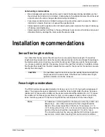
Sensor cable and below ground bypasses
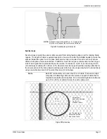
Sensor cable typically passes through conduit that is buried below ground to get from one side of a
gate to the other. There are several techniques that can be used to pull the cable through conduit.
The best method to use depends on a number of site specific factors:
•
the local climate, if the site has a temperate climate and the ground never freezes, split conduit
can be used to protect the sensor cable
•
in areas where ground freezing occurs, solid wall conduit must be used
•
the solid wall conduit must be sealed water tight, at both ends
•
if the cable is being deployed from a cable stand, the cable can be pulled through the conduit
as it is dispensed
•
if the cable is being deployed from a trailer, or truck, or is being walked around the perimeter, it
will have to be pulled back to pass through the conduit
•
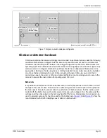
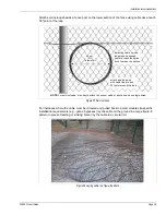
a sufficient amount of cable must be pulled back and laid out in a figure 8 pattern for service
loops, and gate coverage, as required
Installing the sensor cable
1.
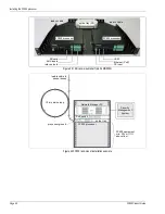
Ensure that there is enough lead-in cable at the processor location to reach the processor
connections and to create a splice point service loop.
2.
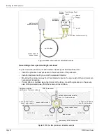
Run the lead-in cable to the designated start point of the first zone. Ensure that there is
enough cable to reach the start module enclosure, add 1 m (3.3 ft.) for the splice and enough
extra cable to create a splice point service loop.
3.
Depending on the zone configuration:
•
For expressed fibers (midspan access used to pass fibers through the enclosure without
cutting the cable) run the sensor cable back to the start point of the zone and leave
enough cable to create a second splice point service loop. Continue deploying the cable.
OR
•
Cut the sensor cable at the start module plus 1 m for the splice, and then add 1 m for the
splice and run the sensor cable back to the start point of the zone and leave enough cable
to create a second splice point service loop. Continue deploying the cable.
4.
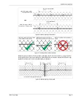
At each point in the installation where extra cable is required, lay out a sufficient amount of
cable in a figure 8 pattern to cover the feature.
If you are pulling the cable around the perimeter, you must pull back a sufficient amount of
cable after the cable is dispensed to cover the cable length requirement for each feature.
5.
Once you have reached the designated end of the zone, leave enough cable to create a splice
point service loop for the fiber termination. Add 1 m (3.3 ft.) for the end module splice.
6.
If the installation ends at this zone’s end module, cut the sensor cable.
OR
If the installation continues past the end of this sensor zone, express the required fibers
through the enclosure and leave enough cable to make a splice and create a splice point
service loop. Then continue deploying the sensor cable.


