Installing the FP400 processor
FP400 Product Guide
Page 43
Processor connections
Sensor cable connections
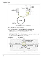
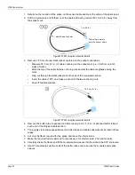
The lead-in cable connections to the processor for each zone use 2 SC/APC connectors with 1 m
leads that are harvested from the zone’s start module. Carefully measure and cut 1 m leads off of
the start module and end module. Retain 2 of the leads for the processor connections. The
remaining leads can be discarded following the installation. To make the connections remove the
plastic cover from the processor connector and plug in the SC/APC connector. Retain the plastic
covers in case the processor has to be disconnected for any reason.
Wiring connections
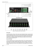
You make the FP400 wiring connections on removable terminal blocks. The screw terminals
accept wire sizes from 12 to 24 AWG, with a 6 mm (¼ in.) strip length. Remove the terminal blocks
to make the wiring connections. Reinstall the blocks after the connections are complete, and
verified.
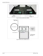
shows the sensor cable to processor connections and the input/output (I/O)
wiring connections.
show the Silver Network wiring options.
Power connection
There are two methods for powering the FP400 processor, screw terminals for a 12 to 48 VDC
power connection or an RJ-45 PoE connection. The PoE connection also serves as a network
interface for Silver Network communications.
Ground connection
The FP400 sensor requires a single ground reference. For surface-mount and post-mount
processors, connect the enclosure ground screw to an approved earth ground. For rack-mount
processors, connect the ground screw on the processor to the rack ground. The earth ground
connection should be stable and noise free. An improper or unstable earth ground can induce
noise in the FP400 sensor.
CAUTION
The two sensor fibers for each zone must be exactly the same length.
Ensure that the two fiber leads are the same length when splicing the
lead-in cable, the start module, and the end module (i.e., measure
carefully and trim if necessary, to match the length of the two fibers).
Note
Outdoor runs of PoE cable and EIA-422 cable can use lightning
arrestors to protect the communication lines.
and
illustrate the use of lightning arrestors on the FP400 comm links.
CAUTION
Consult the local electrical code for grounding information and
requirements.
Do not use the fence structure as an earth ground.
Keep the ground wire as short, straight and direct as possible.


