FP400 configurations
Page 16
FP400 Product Guide
Linear zone configuration
The linear zone configuration is used when the start point and end point of the detection zone are
separated by some distance. In this case, the processor module is connected to the start module
by lead-in cable at the beginning of the sensor zone. The sensor zone runs for up to 300 m to an
end module.
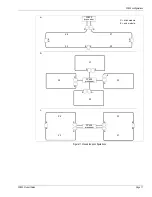
illustrates three block diagrams of FP400 linear configurations, and
shows a back-to-back 8 zone configuration.
Closed loop configuration
The loop configuration provides a closed perimeter. The processor is located within 20 km of the
perimeter fence with two splice enclosures housing the start and end points of the detecting
sensor cable. Non-detecting lead-in cable carries the laser light signals between the processor
and the start module at the beginning of the detection zone. The sensor zone runs for up to 300 m
of detecting cable to the end module.
illustrates three block diagrams of FP400 closed
loop configurations.
The closed loop configuration can be used as a single zone with up to 300 m of detecting cable
(see
). It can also be used with two, three, or four zones providing up to 1.2 km of
detecting sensor cable per processor. With careful planning, the start module and end module
splice enclosures can be located on either side of a gate, with the gate protected by another
sensor technology (e.g., a wireless gate sensor, or a microwave).
Figure 9 Single processor linear zone configurations
Figure 10 Two processor linear zone configuration (8 zones)
S
S
E
S
E
E
S
E
S
E
S
E
E
S
E
S
E
S
S
E
S
E
S
E
E = end modules
S = start module
FP400
processor
FP400
processor
FP400
processor
a
b
c
S
E
S
E
E
S
E
S
E
S
S
E
S
E
S
E
E = end modules
S = start module
FP400
processor
FP400
processor
Z1
Z2
Z3
Z4
Z5
Z6
Z7
Z8


