background image

Installing the sensor cable

Page 16

FlexPI Product Guide

Installing cable on security cages

Figure 2:

 shows a double cable pass installation on a 3 m (10 ft.) security cage.

Use nylon cable ties spaced about 30 cm (12 in.) apart to attach the FlexPI sensor cable to the 
security cage.

Attach the cable ties to the center of each fence link (not at the junctions).

Pull the cable ties until they are hand tight and the cable is snug to the fence.

Attach the sensor cable to the secure side of the cage (the side opposite the threat).

Space the sensor wire evenly on the security cage.

The recommended separation between cable passes on security cages is 1 m (3.3 ft.).

Create 30 cm loops at support posts for increased sensitivity.

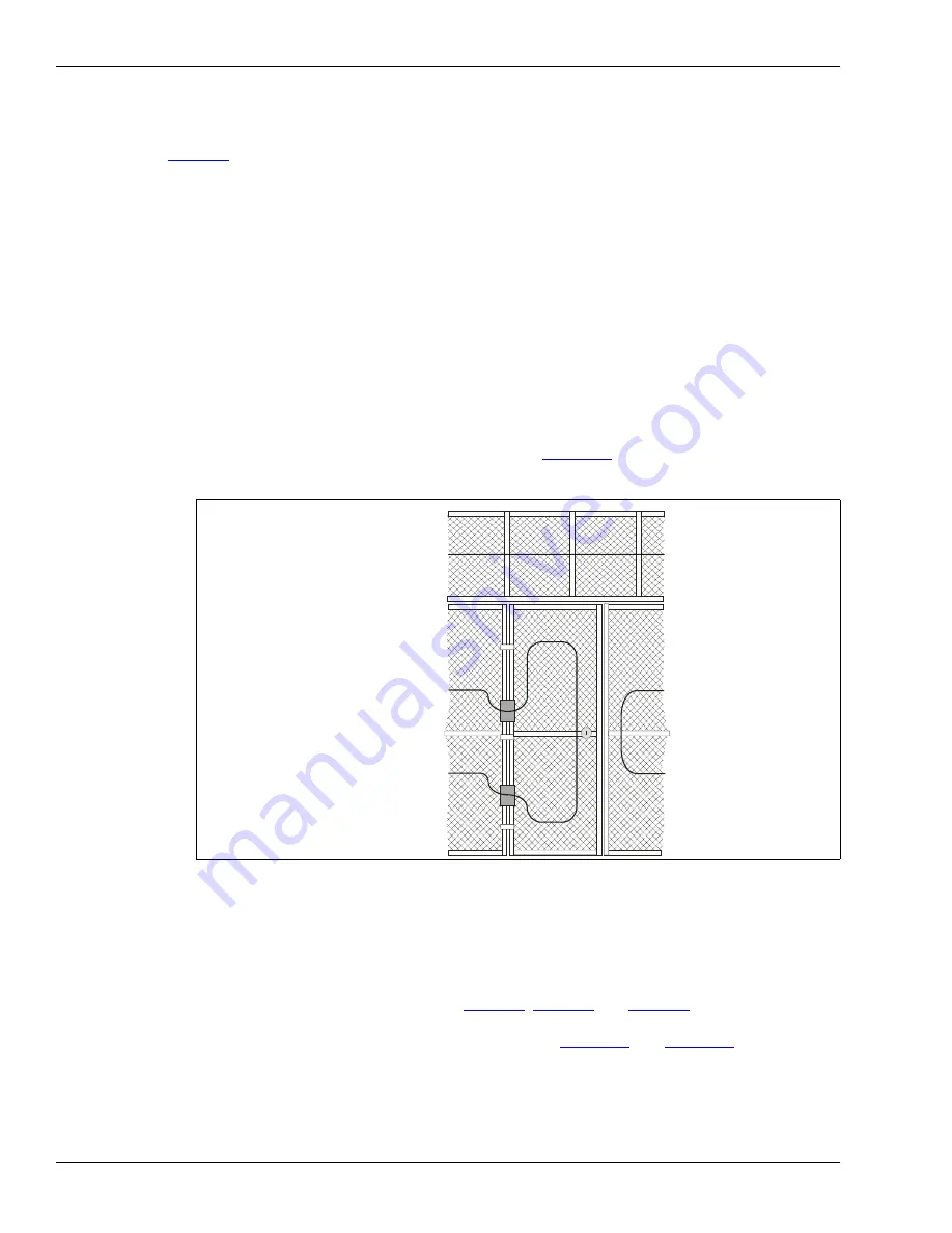
To install sensor cable on security cage doors or gates, run the cable from the cage to the door 
at the hinged side of the door. Ensure that there is enough slack in the cable to allow the door 
to fully open and close. Ensure that the cable cannot be caught and pinched when the door 
closes. Run the cable once completely around the door between 15 and 30 cm from the edge 
of the door. Run the cable from the door back to the cage at the hinged side of the door. 
Continue installing the cable on the security cage. 

Figure 16:

 illustrates sensor cable 

installation on a security cage door.

Installing cable on walls

The cable spacing depends on the type of building material and the required level of security. The 
maximum recommended spacing for any type of wall surface is 1.25 m (4 ft.). The minimum 
recommended spacing is 30 cm (1 ft.) (see 

Figure 3:

Figure 4:

 and 

Figure 5:

). When attaching the 

sensor cable to the mounting surface use fasteners that hold the cable firmly against the surface 
and space the fasteners approximately 30 cm apart (see 

Figure 13:

 and 

Figure 14:

). 

Begin at the processor location, or if using lead-in cable, at the designated start point of the 
zone, and attach the cable to the wall. Leave 0.5 m (20 in.) of sensor cable at the start point, to 
make the connection.

Run the cable along the surface parallel to the floor, using a fastener every 30 cm (1 ft.).

Figure 16: Installing sensor cable on cage doors and gates

use a sheet of rubber to

prevent the cable from being 
caught or pinched when 
the door opens or closes

install sensor cable along
the top section of the cage

continue the cable run on
the other side of the door

run the sensor cable 
around the door app.
30 cm from the edge

run the cable from the cage
to the door on the hinged
side of the door

(if necessary)

Summary of Contents for FlexPI C8DA0402-001

Page 1: ...Product Guide FlexPI Interior Intrusion Detection Sensor C8DA0402 001 Rev B January 13 2014 ...

Page 2: ...dance with the instruction manual may cause harmful interference to radio communications Operation of this equipment in a residential area is likely to cause harmful interference in which case the user will be required to correct the interference at his own expense This device complies with part 15 of the FCC Rules Operation is subject to the following two conditions 1 This device may not cause ha...

Page 3: ...s 10 2 Installation 15 Installing the sensor cable 15 Cable handling 15 Installing cable on security cages 16 Installing cable on walls 16 Installing cable on roofs 17 Installing cable on floors 17 Embedding sensor cable in buildings and walls 17 Protecting windows and skylights 17 Protecting pipes and data cables 17 Installing terminators 18 Splicing cable 19 Outdoor cable installation 19 Install...

Page 4: ...ng the Threshold 32 Setting the cut Count and time Window 33 The Cut Profile 33 Setting the Climb Alarm parameters sustained attack 33 Setting the climb Time and Window 34 Area Preparation 35 Bar graph received signal strength indicator 35 Step 1 Setting the Filter Response 36 Step 2 Calibrating the FlexPI Gain Threshold 36 Setting the Climb Alarm parameters sustained attack 38 Setting the Cut Ala...

Page 5: ...eter most intruders while alerting police or security Each FlexPI system is a self contained intrusion detection sensor consisting of a processor an enclosure up to 600 m of sensor cable and a terminator The cable mounting hardware power supply alarm communication wiring and alarm annunciator are Customer supplied Figure 1 FlexPI system components 300 m sensor cable 30 m lead in cable data cable p...

Page 6: ...se bands that optimize the sensor s response for the protected surface and the expected type of attack Other detection parameters include the Climb Alarm Settings sustained attack the Cut Alarm Settings number of impacts Time Window time in which a sustained attack or the number of impacts must occur to generate an alarm Gain Settings four discrete signal amplification levels FlexPI also includes ...

Page 7: ...ermine the security requirements and expectations for a FlexPI installation There are a number of factors which must be considered when planning the installation The primary factors are the value of the assets being protected and the required level of security For a high security application where a sophisticated attack is possible the sensor cable spacing should be kept at a minimum This will inc...

Page 8: ...cm 1 ft Keep roofs separate from other parts of the installation For roof installation on steel beams the maximum recommended cable spacing is 1 8 m 6 ft On roofs with wooden trusses the cable spacing should match the spacing of the trusses typically 61 cm 2 ft Sensor cable can be installed directly on the underside of a roof s surface For increased security use additional cable passes on the lowe...

Page 9: ...structure or to the floor As with other parts of the building the type of building material dictates the number of cable passes required Embedding sensor cable With careful planning the sensor cable can be embedded in walls floors or even roofs during construction The recommended method is to install metal conduit inside the structure during the construction phase When the construction is complete...

Page 10: ...e to the mounting surface must hold the cable firmly against the surface without pressing into the jacket or damaging the cable The fasteners must be appropriate for the specific type of surface Figure 2 Double pass security cage installation use cable loops at support posts for increased sensitivity double cable pass using 1 m spacing on 3 m security cage 30 cm 12 in recommended cable tie spacing...

Page 11: ...w security application single pass on 8 ft wall 61 cm 2 ft 61 cm 2 ft 61 cm 2 ft 61 cm 2 ft 2 44 m 8 ft terminator FlexPI processor sensor cable power data cable 81 cm 2 7 ft 81 cm 2 7 ft 81 cm 2 7 ft 2 44 m 8 ft terminator FlexPI processor sensor cable power data cable 1 22 m 4 ft 1 22 m 4 ft 2 44 m 8 ft terminator FlexPI processor sensor cable power data cable ...

Page 12: ...nduit terminator FlexPI processor sensor cable power data cables sensor cable around windows 1 2 2 m terminator FlexPI processor sensor cable 61 cm 2 ft 3 ft reduced cable spacing on lower portion of roof NOTE Cable installed indoors on 4 f t 91 cm the underside of the roof sensor cable cable tie 30 50 cm data cable conduit sensor cable metal conduit fastener 1 m 3 25 ft max sensor cable ...

Page 13: ... cable with permanent tape cable tie 30 cm sensor cable 12 in support post sensor cable 30 cm 12 in cable ties do not allow the sensor cable to be pinched between the post and the cage If the cage is tightly secured to the post wrap the cable around the post as illustrated cable clip sensor cable 30 cm 12 in cable clip mounting surface fastener sensor cable permanent tape 30 cm sensor cable 12 in ...

Page 14: ...Page 14 FlexPI Product Guide Figure 15 Using corner loops 10 15 cm inside corner outside corner 4 6 in corner loop fastener 10 15 cm 4 6 in corner loop ...

Page 15: ...g is a list of cable handling Do s and Don ts Apply consistent light tension approximately 2 25 kg 5 lbs while mounting the sensor cable Install the sensor cable in metal conduit if the cable is being installed in an area where it may be prone to damage from vandalism equipment or materials see Figure 10 DO NOT use plastic conduit When using cable ties to attach the sensor cable to a security cage...

Page 16: ... at the hinged side of the door Continue installing the cable on the security cage Figure 16 illustrates sensor cable installation on a security cage door Installing cable on walls The cable spacing depends on the type of building material and the required level of security The maximum recommended spacing for any type of wall surface is 1 25 m 4 ft The minimum recommended spacing is 30 cm 1 ft see...

Page 17: ...y heavy rain Installing cable on floors Attach the cable to the underside of the floor either directly to the subfloor or to the support structure Base the number of cable passes required on the type of floor Embedding sensor cable in buildings and walls This type of installation requires the installation of metal conduit inside the walls during the construction of the building Senstar recommends ...

Page 18: ...fully separate the strands of the exposed braided shield Tightly twist the strands into a single conductor and then carefully remove 6 mm 0 25 in of insulation from the center conductor DO NOT nick the center conductor Insert the twisted shield into one of the terminals on the terminal block and tighten the screw Insert the center conductor into the adjacent terminal and tighten the screw Insert t...

Page 19: ...als and tighten the screws Insert the 2 center conductors into the 2 adjacent opposing terminals and tighten the screws Ensure that shield meets shield and center conductor meets center conductor Line up the terminal block with the center of the splice enclosure and apply 3 or 4 wraps of electrical tape at each of the 2 points where the cable will fit into the cable guide bars Align the 2 taped se...

Page 20: ...away from the beginning of the zone by connecting lead in cable to the processor and splicing the lead in to the sensor cable There are two flanges on the enclosure that include 5 mm 0 375 in holes for mounting the enclosure on a flat stable surface Figure 20 illustrates the FlexPI processor features and Table 1 includes feature descriptions Figure 21 shows a mounted enclosure The mounting hardwar...

Page 21: ...THRESHOLD switch Sets the input signal amplification before the signal is processed 4 settings from 1 low to 4 high 12 Enclosure cover mounting holes X4 4a GAIN THRESHOLD LEDs 4 LEDs correspond to 4 Gain settings LED ON switch ON 13 T4 SENSOR CABLE connection GND SHIELD connect twisted braided shield FLEX IN CENTER connect center conductor 5 S5 MISC switch miscellaneous controls S5 1 sets the freq...

Page 22: ...Installing the processor Page 22 FlexPI Product Guide Figure 21 Enclosure mounting mounting hardware sensor cable alarm data cable and power cable ...

Page 23: ...4 Sensor cable and lead in cable connections are made exactly the same way Figure 22 illustrates the sensor cable connection procedure Pass the sensor cable or lead in cable through the left side cable gland Prepare the cable for connection by following steps 1 2 and 3 in Figure 17 Figure 22 Connecting the sensor cable lead in cable 4 5 Insert the terminal block into T4 Insert the twisted shield a...

Page 24: ...s are complete and verified Figure 23 shows the sensor cable to processor connection procedure Figure 24 shows the input output wiring connections to the FlexPI processor Figure 23 Connecting the data and power cables 2 3 1 Feed the data and power cable through the right Replace terminal block T5 and tighten the cable Carefully remove 6 mm 0 25 in of insulation side cable gland remove terminal blo...

Page 25: ...ns sensor cable relay output and RELAY CONNECTIONS 30V 0 5 A RELAY T5 PWR INPUT 12 48 VDC T4 SUPERVISION SONALERT ALARM NC COM NO NC COM NO COM NO FLEX IN GND VDC VDC ALARM NO ALARM COM ALARM NC SONALERT NO SONALERT COM SUPERVISION NO SUPERVISION COM SUPERVISION NC SHIELD CENTER power input connections ...

Page 26: ...Installing the processor Page 26 FlexPI Product Guide ...

Page 27: ...ter Settings sets the sensor s frequency response Sensitivity Switch SW2 Gain Threshold Settings S4 Gain Settings Cable sets the amplification of the input signal received from the sensor cable before processing Impact Count Selector JP4 Cut S3 Cut Alarm Settings Window sec Threshold Count Cut Profile Sets the number and intensity of discrete impacts which must occur within the specified time Wind...

Page 28: ...cted surface For example To simulate an impact attack Cut Alarm strike the surface using moderate to strong force with a hard object such as the handle or blade of a large screwdriver Wait approximately two seconds between impacts and wait about four seconds after each Cut Alarm to allow the processor s filters to clear To simulate a sustained attack Climb Alarm on a hard surface e g brick cinder ...

Page 29: ...justments before changing the processor s settings First make the changes using the calibrate tool Then view a magnitude or frequency response plot using the new settings while testing the installation If the changes do not result in the required level of detection continue making and reviewing adjustments When the results are satisfactory download the new parameters to the processor CAUTION Some ...

Page 30: ...ned activity is added to the total Time 10 Time Sets the period of Time that the received signal must exceed the climb Threshold to cause an alarm The Time must be accumulated within the climb alarm Window setting 2 sec Filter Settings The filter settings are used to customize the sensor s frequency response to the type of mounting surface and the installation environment Correct adjustment of the...

Page 31: ...the length of the cable 6 Once the Frequency response is adequate close the Calibrate tool save the UCM file and download the new settings to the processor Step 2 Calibrating the Gain Settings The Cable Gain is used to amplify the input signal from the sensor cable before it is processed FlexPI has four Cable Gain Settings ranging from 1 lowest to 4 highest 1 Using the sensor s default Gain Settin...

Page 32: ... surface 2 If any of the attack simulations impacts do not register as Cut Counts lower the Cut Alarm Threshold 3 Repeat this process until each simulated attack impact registers as a Cut Count and leads to an alarm 4 Once the Threshold is set monitor the system for nuisance alarms If the nuisance alarm rate NAR is unacceptable try to determine and correct the source Otherwise raise the Threshold ...

Page 33: ...arm parameters sustained attack 1 Start recording a UCM Magnitude response plot tool and perform the simulated sustained attack scenario along the protected surface 2 If the attack simulation does not cause an alarm lower the Climb Alarm Threshold and repeat the tests 3 Repeat this process until the simulated attack always causes a Climb alarm 4 Once the Threshold is set monitor the system for nui...

Page 34: ... also affect the Cut Alarm Settings If the Cut Alarm parameters have already been set retest and if required adjust the Cut Alarm parameters after changing the Cable Gain setting Note For settings available via the UCM that are not adjustable using the onboard switches the default values listed in the UCM apply Figure 26 Calibration switches S1 CLIMB S2 TIME WINDOW S3 CUT S4 GAIN THRESHOLD S5 MISC...

Page 35: ...oring sawing cutting digging chiselling climbing If the Time Window lapses before the Time setting is exceeded the processor resets both parameters S2 Time Window Sets the maximum time in which the specified Climb Time must accumulate to cause an alarm AND Sets the maximum time in which the specified number of Cuts impacts must occur to cause an alarm 8 to 128 seconds S3 Cut Sets the number of imp...

Page 36: ...length of the sensor cable Look for a response that is above the Threshold 6th LED is illuminated but below the top of the bar graph 10th LED is OFF 4 If the signal response does not illuminate the green LED increase the Gain setting one level and repeat the test OR If the signal response always reaches the top of the bar graph decrease the Gain setting one level and repeat the test 5 When the imp...

Page 37: ...he switches conduct tests sensor alarms raise gain monitor NAR too many NAs calibration complete lower gain too many NAs sensor alarms change frequency response band reset gain to 2 and return to first conduct tests calibrate via UCM OR redeploy cable and repeat procedure conduct tests N Y Y N N Y Y N monitor NAR NAR nuisance alarm rate NAs nuisance alarms gain already at maximum N Y N Y both resp...

Page 38: ...is 4 impacts and the Time Window is 32 seconds If the security regulations at your facility do not define specific Cut Count and Time Window settings then these parameters should be set according to the probability of nuisance impacts occurring within a specific timeframe For example if nuisance impacts can occur but never in rapid succession then the Cut Count can be set to 2 with a short Time Wi...

Page 39: ...e is an advanced parameter which can be adjusted only through the UCM For switch calibration the Cut Profile is ON at the default setting of 20 This means that each time an Impact is recorded 20 of the Climb Window setting is added to the time remaining in the Climb Window see Figure 29 Note If there no Gain Threshold setting functions for both Cut alarm and Climb alarm detection change the Filter...

Page 40: ...rm Figure 30 illustrates the Climb Alarm concept of a sustained attack within a specified time Figure 29 Understanding the Cut Alarm Figure 30 Understanding the Climb Alarm Threshold 10 time Window 30 10 20 5 15 30 29 28 27 26 25 24 23 22 21 20 19 18 17 16 15 14 13 12 11 10 reset counter Threshold 10 time Window 30 Cut Profile 20 add 6 seconds for each count 10 20 5 15 30 29 28 27 26 25 24 23 22 2...

Page 41: ... with black jacket 300 m 984 ft reel when ordering allow for an overage of 5 30 m lead in cable G5SP0201 Non sensitive lead in cable with black jacket 30 m 98 ft reel FlexPI accessories termination splice kit C6KT2600 single zone termination splice kit cable ties GH0916 nylon tie wraps 1000 piece bag double loop bar ties 82 130020 steel bar ties 15 cm 6 in long 18 AWG 1000 pieces UCM software UCM ...

Page 42: ...Page 42 FlexPI Product Guide ...

Page 43: ...ontrols calibration adjustments via the Universal Configuration Module software application calibration adjustments via onboard switches adjustable filter settings frequency response Alarm outputs 2 form C relays rated 30 VDC 1 A max non inductive load 1 ALARM relay activates to signal sensor alarm condition 1 SUPERVISION relay activates to signal enclosure tamper condition cable fault condition p...

Page 44: ...on Alarm LED Alarm LED UCM connected LED Enclosure door open LED Supervision mechanical enclosure tamper switch sensor wires lead in cable processor operation Temperature 0º to 70ºC 0º to 158º F Relative humidity 0 to 95 non condensing Frequency response switch selectable frequency response bands 100 300 Hz 300 900 Hz UCM adjustable frequency response band 100 900 Hz ...

Reviews: