Splicing cable
FlexPI Product Guide
Page 19
Splicing cable
Cable splices are made the same way for sensor cable to sensor cable splices and for lead-in
cable to sensor cable splices. Begin by installing the cables to the point where the splice will be
made. Follow steps 1, 2 and 3 from the termination procedure to prepare the two cables for
splicing (see
). For outdoor cable-splices you must create 15 cm (6 in.) drip loops (see
Outdoor cable installation
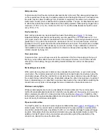
Figure 18: Splice-connecting sensor cable
Figure 19: Creating drip loops for outdoor terminations/splice-connections
7
6
4
5
8
Insert the 2 twisted shields into 2 opposing terminals, and
tighten the screws. Insert the 2 center conductors into the
2 adjacent, opposing terminals, and tighten the screws.
Ensure that shield meets shield and center conductor
meets center conductor.
Line up the terminal block with the center of the splice
enclosure, and apply 3 or 4 wraps of electrical tape* at each
of the 2 points where the cable will fit into the cable guide bars.
Align the 2 taped sections of cable with the 2 cable guide bars,
and press the terminal block into the center of the gel cavity.
Press the taped sections of cable firmly into the cable guide bars.
Do not remove the gel from the enclosure.
Snap the enclosure shut ensuring that both tabs are locked
into the respective slots.
Attach the enclosure to the protected surface using appropriate
fasteners.
(*Or use 2 cable ties.)
termination
splice-connection
15 cm (6 in.)
15 cm (6 in.)


