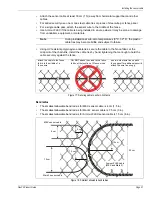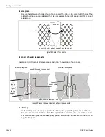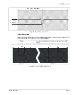
Perimeter layout guidelines
FlexPS Product Guide
Page 19
Armour-FLEX
Armour-FLEX is FlexPS sensor cable encased in a flexible metallic conduit. There are two types of
Armour-FLEX cable, MEX and Mark 2. Armour-FLEX protects the sensor cable from damage and
vandalism, as well as from the sun and weather. Steel cable ties or wire ties are the recommended
fasteners for Armour-FLEX, although UV resistant cable ties can also be used. Armour-FLEX is
available in lengths of 100 meters (328 ft.). Up to three lengths can be spliced together to create a
300 meter (984 ft.) cable. Armour-FLEX splices must be enclosed inside outdoor rated electrical
junction boxes (condulets). Refer to the
Sensor cable selection rules on page 13
to select the
correct type of Armour-FLEX cable for your application.
Processor location guidelines
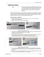
The FlexPS processor can be mounted outdoors on a post, either on, or separate from, the fence
on which the sensor cables are installed (see
). A rigid fixed post is recommended for
outdoor applications. The maximum distance away from the fence that the processor can be
installed is determined by the non-sensitive lead-in cable length (see
). The FlexPS processor can also be installed indoors or outdoors
on a flat stable surface. A post-mount kit is available for post sizes from 4.5 cm to 12.7 cm (1.75 in.
to 5 in.). The hardware required for mounting the processor on a flat surface is customer-supplied.
For installations in which the enclosure must be locked, there is a lockable mounting kit available.
The lockable kit can be used to post-mount or surface mount the FlexPS enclosure.
AC/DC Power source and wiring
The FlexPS processor operates on a wide range of input voltages (12 to 48 VDC). The power
supply, the number of processors, and the lengths of the power cable runs will determine the
gauge of the power cable wiring. In locations where AC power may not be stable or reliable, an
uninterruptable power supply (UPS) should be used for primary power. The following tables
include power cable/load recommendations for 24 VDC and 48 VDC power supplies. The table
assumes a maximum power consumption of 2 W per processor (with NIC and backup battery).
Figure 10: Processor location/ start point overlaps
service loop overlap for fence-mounted processor
lead-in cable
earth ground
1.5 m overlap for post-mounted processor
(consult the local electrical code for grounding requirements)
earth ground


