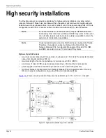
Installing the sensor cable
Page 38
FlexZone Product Guide
Processor connections
See
Cable preparation (all connections) on page 37
for steps 1 - 6.
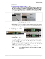
7. Trim the twisted braided shields and the center conductor to a length of 6 mm (1/4 in.) past the
end of the clear tube.
8. Remove the A Side terminal block from T9. Connect the A Side cable to the three position
terminal block by inserting the center conductor and the two twisted braided shield conductors
into the terminal block and tightening the screws. The center conductor goes into the center
(second) terminal.
9. Repeat this procedure for the B Side sensor cable.
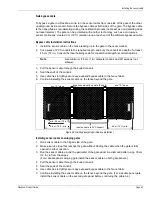
10. Pull the sensor cables back out through the cable glands until they are the correct length to
plug into T9 (A Side to terminals 1, 2, 3; B Side to terminals 4, 5, 6). Tighten the cable glands.
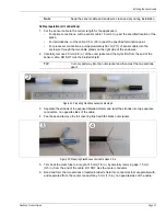
Figure 36: Preparing FlexZone sensor cable steps 5 & 6
Note
Sensor cable splices on page 39
For terminations proceed to
Sensor cable terminations on page 40
Figure 37: Processor sensor cable connections steps 7 & 8
Figure 38: Processor sensor cable connections step 10
A Side
B Side

