Installing the FlexZone processor
FlexZone Product Guide
Page 57
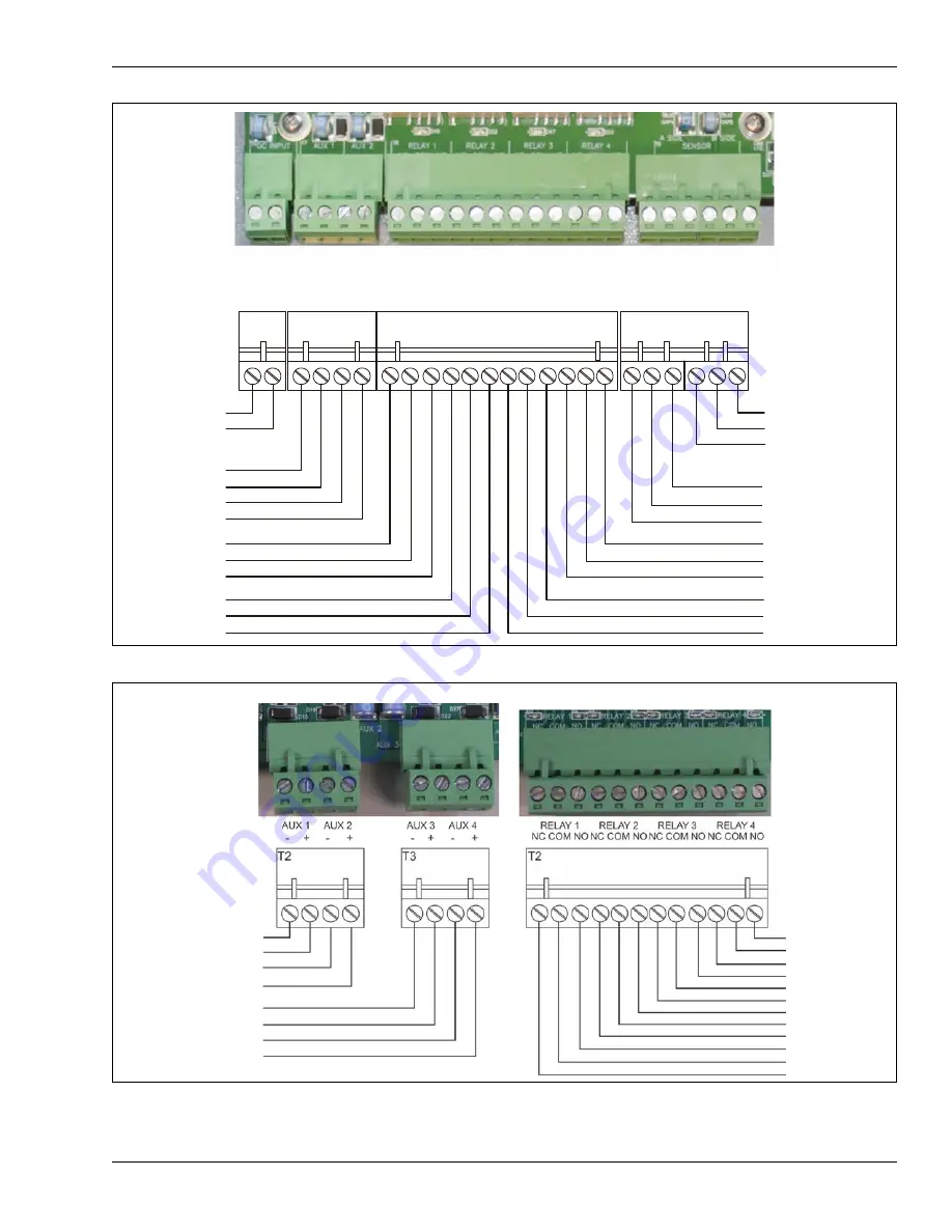
Figure 66: FlexZone processor wiring diagram
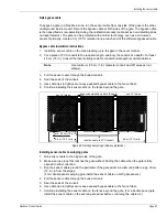
Figure 67: FlexZone option card wiring diagram
T7
T4
T8
-
+
T9
AUX 1
- +
AUX 2
- +
RELAY 1
NC COM NO
RELAY 2
NC COM NO
RELAY 3
NC COM NO
RELAY 4
NC COM NO
A-SIDE
B-SIDE
POWER
-
+
-
-
+
-
T7
T4
sensor cable
T8
T9
relay outputs
self-test/auxiliary
inputs
power
input
A-Side
B-Side
- DC GND
+ 12 to 48 VDC
auxiliary/self-test inputs
-
+
AUX input 1
-
+
AUX input 2
relay 1 NC
relay 1 COM
relay 1 NO
relay 2 NC
relay 2 COM
relay 2 NO
relay 4 NO
relay 4 COM
relay 4 NC
relay 3 NO
relay 3 COM
relay 3 NC
+ center conductor
- shield
B SIDE sensor cable
+ center conductor
- shield
A SIDE sensor cable
- shield
- shield
T4 power output for
processors receiving
power over sensor
cables
ROC outputs
DRIC inputs
auxiliary inputs
-
+
OPT input 1
-
+
OPT input 2
OPT 4 NO
OPT 4 COM
OPT 4 NC
-
+
OPT input 3
-
+
OPT input 4
OPT 3 NO
OPT 3 COM
OPT 3 NC
OPT 2 NO
OPT 2 COM
OPT 2 NC
OPT 1 NO
OPT 1 COM
OPT 1 NC


