Installing the sensor cable
FlexZone Product Guide
Page 39
Sensor cable splices
See
Cable preparation (all connections) on page 37
for steps 1 - 6.
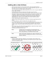
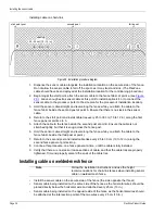
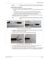
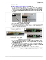
7. For splice connections bend and form the section of twisted braided shield on the left side of
the cable into a conductor that is parallel with, and separated from, the center conductor by
5 mm (1/5 in.). Trim the second section of twisted braided shield flush with the black jacket.
8. Trim the twisted braided shield and center conductor to a length of 6 mm (1/4 in.) past the
clear tube.
9. Repeat this procedure for the second sensor cable.
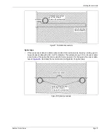
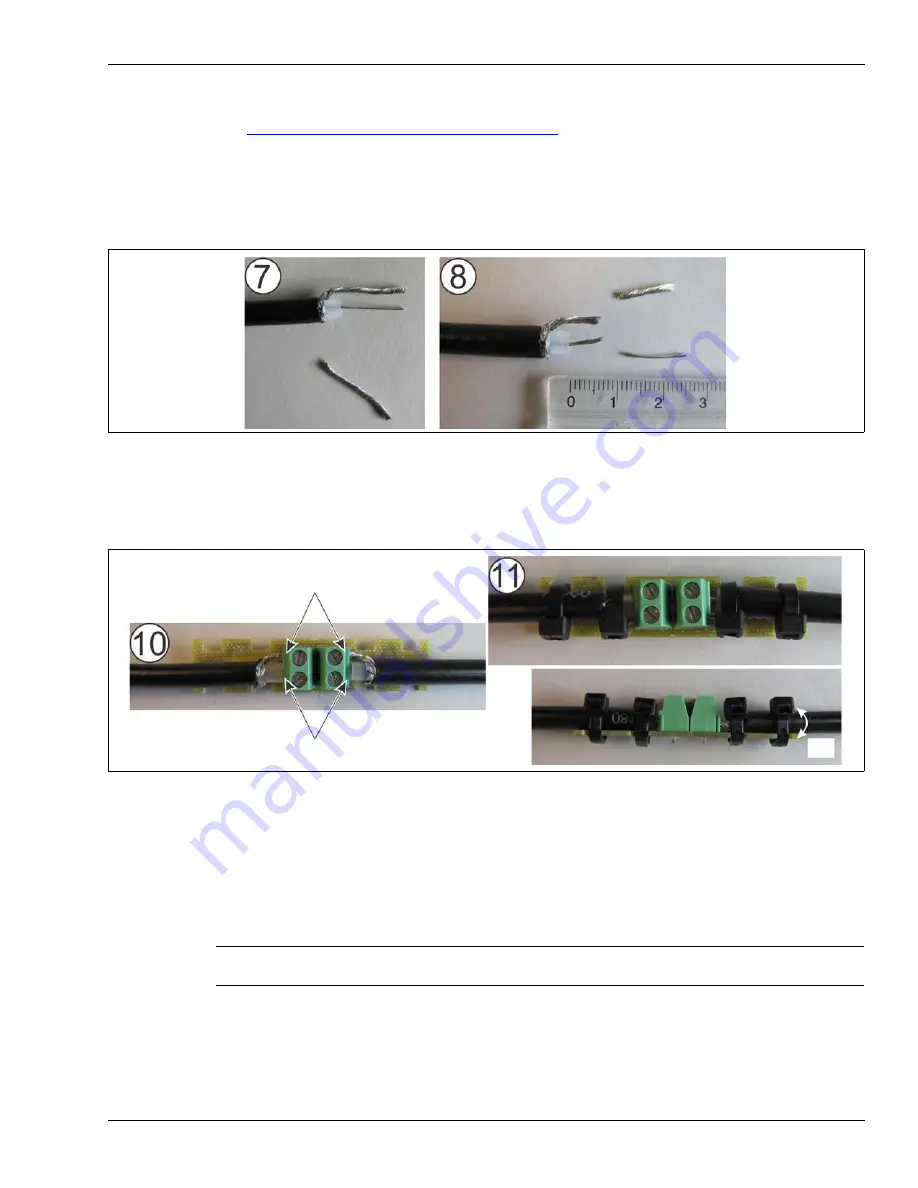
10. Insert the center conductors into opposing terminals on the splice circuit card assembly (CCA)
and tighten the screws. Insert the twisted braided shields into the adjacent opposing terminals
on the splice CCA, and tighten the screws.
11. Secure both sensor cables to the splice CCA using the supplied cable ties. Ensure that the
heads of the cable ties are all on the same side of the CCA and that they are at a 45º angle
from the flat plane of the CCA.
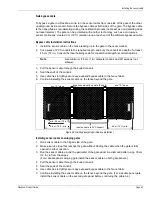
12. Line up the splice CCA so it is centered between the dual cable guide bars, and press the
assembly firmly into the gel snap enclosure. Press the sensor cable into the cable guide bars.
DO NOT remove the protective gel inside the enclosure.
13. Snap the enclosure shut ensuring that both tabs are securely locked in the slots.
Figure 39: Sensor cable splices steps 7 & 8
Figure 40: Sensor cable splices steps 10 & 11
Note
The weather-proofing protective gel should be oozing out of the gel
snap enclosure.
45º
insert the twisted braided shields into opposing
insert the center conductors into opposing
terminals and tighten the screws
terminals and tighten the screws


