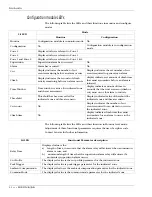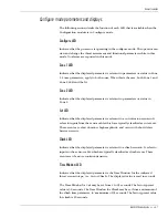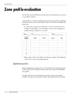
Configuration settings
7 - 4 • • • Intelli-FLEX II product guide
3. To simulate a cut event, tap the fence once with a medium size screw driver,
approximately 20 cm (8 in.) long, at the intensity level at which minimum
detection is desired. See
Tapping the fence
.
The level reading captured on the Configuration module display should be
between
20
and
30
.
Figure 7-2: Adjusting the gain
4. If the Level displayed is less than
20
, increase the gain by turning R19, on the
processor board, slightly clockwise.
If the Level is more than
30
, decrease the gain by turning R19, on the
processor board, slightly counter-clockwise.
If the Level is between
20
and
30
continue to the next step.
5. Tap the fence again as close to the same intensity as before.
6. Repeat steps 3 through 5 until the Level readings consistently fall within a
range of
20
to
30
. If you obtain a reading between
20
and
30
, at least four out
of five times, the gain is properly set.
Gain setting procedure - Zone 2
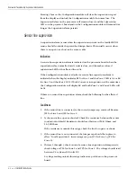
To check and adjust the gain for zone 2 proceed as follows:
1. Press
Display Select
to select Zone 2.
The
Zone 1
LED goes off and the
Zone 2
LED turns on. You are now ready to
view the level in Zone 2.
2. If zone 2 is on the same type of perimeter fence as in zone 1, preset R26, on
the processor board, to the same physical position as R19, before proceeding.
3. Procedure as in steps 3 to 5 in for Gain setting procedure - Zone 1, but adjust
R26, on the processor board, instead of R19.
4. Exit the level mode by pressing
Function Select
. This will toggle the
Configuration module back to the Monitor mode display.

