background image

Perimeter layout guidelines

Intelli-FLEX II product guide  •  •  •  4 - 11

Fence corners and heavier gauge posts

Corner posts are usually more sturdy than the regular fence support posts, and 
often are braced. Heavier gauge posts can occasionally be found in the middle of 
a fence section, as well. An intruder may be able to climb over the fence at these 
points without causing as much fence vibration as at other points along the fence.

Allow enough additional sensor cable to install cable loops at corner posts and at 
any heavier gauge posts in the protected fence. This will increase the detection 
sensitivity at corner posts and heavier gauge posts. (See also 

Service loops 

)

Palisade fences have a uniform construction along the entire fence line including 
the corners, unlike chain-link or weld-mesh fences. Therefore, no special sensor 
cable deployment is required at corners.

Service loops

Service loops provide lengths of extra cable to allow repair of damaged cable 
without the need to splice in a section of cable. 30 to 45 cm (12 to 18 in.) of cable 
should be allotted approximately every 15 to 61 m (50 to 200 ft.) along a cable 
run for a service loop. 

The U-shaped loop should be located at a fence post whenever possible.

Due to the nature of the sensor cable deployment, it may be difficult to deploy 
service loops on a palisade fence.

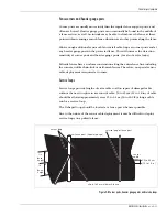
Figure 4-8 Corner posts, heavier gauge posts, and service loops

corner fence post (heavier gauge)

sensor
cable

chain-link or weld mesh fence

corner loop

30 to 45 cm
(12 to 18 in.)

service loop at fence post

1/4

1/4

fence

height

fence

height

Summary of Contents for Intelli-FLEX II

Page 1: ...Intelli FLEX II Perimeter Protection System Relay Output Processor Product Guide C6DA0602 001 Rev K First edition October 9 2008 ...

Page 2: ...al apparatus meets all requirements of the Canadian Interference Causing Equipment Regulations Cet appareil numérique de la classe B respecte toutes les exigences du Règlement sur le matériel brouilleur du Canada USA This device complies with part 15 of the FCC Rules Operation is subject to the following two conditions 1 This device may not cause harmful interference and 2 this device must accept ...

Page 3: ... Optional components 3 7 4 Site planning Site planning guidelines 4 1 Site Survey 4 2 Upgrade existing structures 4 3 Perimeter layout guidelines 4 8 Equipment requirements 4 17 5 Installation instructions Overview 5 1 Basic sensor cable installation 5 2 Cable installation on different fence types 5 9 Installation of cable at gates 5 13 Gate bypass module 5 23 Cable devices 5 34 Installing the Int...

Page 4: ...bleshooting a 2 Supervision related problems a 3 Detection problems a 7 False Nuisance alarm problems a 10 Power problems a 12 Configuration module problems a 15 b Spare parts list c Component specifications Intelli FLEX II Processor c 1 Gate bypass module c 2 Glossary Index Mark 2 sensor cable installation procedure Introduction 1 Cable stabilization procedure 1 Sensor cable installation guidelin...

Page 5: ... to report sensor alarms and supervision status via relay contacts Features Easy to install Low cost highly sensitive consistent detection State of the art microcontroller based processor User definable configuration parameters Detachable configuration module Discriminates between intrusion attempts and weather related events Lightning EMI and RFI protection Separate relay outputs for intrusion al...

Page 6: ...de Purpose of this guide This is the product guide for the Intelli FLEX II DC DC powered relay output processor This guide includes information to assist you in selecting installing calibrating and maintaining the components of your Intelli FLEX II system ...

Page 7: ...they could be caused by an intruder attempting to penetrate the perimeter by climbing over lifting or cutting through the fence The Intelli FLEX II processor evaluates the signals and discriminates between actual intrusion attempts and weather related events The Intelli FLEX II system monitors the processor s power level If there is a significant fluctuation in the power a supervision alarm will b...

Page 8: ...eshold is exceeded is greater than the preset cut count and the preset cut count is exceeded within the preset cut window time frame When the fence fabric is cut an impulse of energy produces a high initial amplitude signal that exceeds the cut threshold Each time the cut threshold is exceeded a cut event is recorded Cut activity will activate a cut counter The cut counter has a preset number of c...

Page 9: ... climb counter resets If the number is exceeded the system identifies the activity as an intrusion attempt and will generate a climb alarm System supervision The Intelli FLEX II system monitors itself to ensure that its protection capability is not compromised If that capability has been compromised the system will generate a supervision alarm Supervision alarms can occur for several reasons a sen...

Page 10: ...ge required to operate the system reliably 8 VDC a low DC voltage condition occurs When this happens the alarm and supervision relays for both zones activate and the entire system shuts down Once the DC voltage on the 12 volt line increases to at least 11 VDC the condition will clear and the system will resume operation Tamper The Intelli FLEX II system uses a solid state sensor to detect if the e...

Page 11: ...n sensitive feed cable power supply cable terminator kit configuration module order separately Zone 1 Zone 2 Cut Climb Time Window Threshold Cut Count Climb Time Display Select Increase Decrease Load Self Test Configure Monitor Mode Select Alarm Supervision Clear Level Relay Time Cut Profile Peak Trigger Ambient Comp Common Mode Function Select Intelli FLEX zone 2 zone 1 dual zone processor 24 VDC...

Page 12: ...le 305 meters 1 000 feet per zone For a single cable pass installation with service and corner loops included this means that approximately 575 m 1885 ft of fence can be monitored by one dual zone processor Non sensitive feed cables are spliced together with the sensor cables and connected to the processor at the F connectors located at the top of the processor card The terminal blocks along the b...

Page 13: ... Non sensitive feed cable The non sensitive coaxial feed cable does not detect vibrations It is used primarily in two instances In both cases the non sensitive feed cable allows the signals that are generated through the sensor cable to be routed to the processor The sensor cable cannot be connected directly to the processor therefore a section of non sensitive feed cable complete with an F connec...

Page 14: ...device that enables the supervision current to pass through the sensor cable It is installed at the end of the sensor cable away from the processor Cable splice Figure 3 4 Cable splice The cable junction device is a moisture proof splice kit It is used to splice non sensitive feed cable to sensor cable or to connect two pieces of sensor cable together ...

Page 15: ...cated low voltage DC power source 18 to 56 VDC DC power float charger and rechargeable battery The DC power float charger is the most feasible option when AC power is convenient and the AC power receptacle is protected from the weather The DC power float charger is merely plugged into the AC power source and 12 VDC is applied to the processor in parallel with a 12 VDC Gel Cell battery This is ofte...

Page 16: ... power UPS When the central low voltage power supply is used it should be powered from a non interruptible source of AC power This power source will usually be provided for the computer system that is often a part of larger installations or will be part of a UPS system for the overall security system If a UPS system is not already a part of the overall security installation a small standalone UPS ...

Page 17: ...e cable line A supervision alarm is generated when the cable line is opened Gate bypass module The Intelli FLEX Gate bypass module is used to bypass a protected gate without triggering an intrusion alarm The module operates in secure and access modes When the unit is in secure mode the gate is monitored by the system It acts as any other section of protected fence and an alarm triggers whenever an...

Page 18: ...te bypass module are available Model 2490 1 manual or local operation keylock switch Model 2490 2 remote operation remote controlled relay Figure 3 7 Local and remote gate bypass modules MODEL 2490 2 Local gate bypass module Remote gate bypass module SECURE ACCESS MODEL 2490 1 ...

Page 19: ... visual inspections of all detection zones will provide years of effective operation Site planning includes four main steps These steps will be detailed in the following sections For installation guidelines refer to Chapter 5 Installation instructions survey site Site Survey on page 4 2 upgrade existing structures as necessary Upgrade existing structures on page 4 3 layout components on site plan ...

Page 20: ...ude fences gates buildings etc Check that the mounting surfaces are in compliance with established standards with respect to stability location of obstacles such as vegetation Figure 4 1 Sample site plan Z1 Z2 Z3 Z4 Z5 Z6 Z7 Z8 Z9 proc 4 proc 1 proc 2 proc 3 terminator typical sally port gate included in Z6 microwave sensors main building swinging gate included in Z3 NOTE not required gate disconn...

Page 21: ...fence detection systems the fence condition is critical to the trouble free efficient operation of the Intelli FLEX II sensor Breaks in the fence structure or slack areas in the fence fabric will inhibit the transmission of the fence vibrations to the sensor cable The fence must be properly installed maintained and tensioned to provide effective intrusion detection with the Intelli FLEX II sensor ...

Page 22: ...rt for all posts rails braces and tension wires Tighten stretcher bar bands wire ties and any other fasteners very securely None of the fabric should be free to move Any fence movement which can cause metal to metal contact may be a potential source of nuisance alarms Tension wires can be installed horizontally to stiffen the fence fabric These wires should be secured at each post so they will not...

Page 23: ...nstall the cable that hides the cable and protects it from the elements tampering or other potential damage Unlike chain link or weld mesh fences palisade fences have a uniform construction along the entire fence line including the corners If constructed properly a palisade fence conducts vibrations well and any attempt to cut into the fence will be detected Because the fence is rigid climb over i...

Page 24: ...ot welded Loose or rattling equipment should be fastened down or removed The use of barbed tape is NOT recommended It is difficult to fasten tape to prevent noise generation If barbed tape must be used every effort should be made to minimize noise generated from the movement of the tape This requires tying the barbed tape at specific points where motion can cause the tape to touch the fence Other ...

Page 25: ...me types single swinging double swinging and sliding are covered in this guide Obstacles All vegetation weeds brush trees etc must be cleared from the fence area It cannot in any way touch or hang over the fence fabric Any other objects that will rattle or otherwise affect the operation of the sensor cables must be removed from the perimeter Weather Ambient weather conditions such as a tendency fo...

Page 26: ... layout of cable in each zone Intelli FLEX II dual zone processors optional equipment cable connectors indicate type of connector splice terminator power supply indicate type of power supply and power distribution plan communications system wiring plan Cable layout guidelines This section provides the information required to determine the amount of cable required to install your Intelli FLEX II sy...

Page 27: ...r cable should follow the ground contour to maintain a constant height above the ground Fence height considerations Figure 4 5 Cable installation height recommendations The following cable layouts are recommended depending on fence height for fences up to 2 5 m 8 ft tall a single pass of sensor cable for fences greater than 2 5 m and less than 4 5 m in height and on vinyl coated fence a double pas...

Page 28: ...attached to the upper and middle support On palisade fences greater than 2 m 6 ft 6 in in height an alternative method of cable deployment is recommended Usually such fences have three horizontal supports Outrigger arrays Figure 4 7 Cable installation on barbed wire outrigger array In a barbed wire outrigger array if the wires in the array are less than 10 cm 4 in apart the sensor cable will be la...

Page 29: ...s have a uniform construction along the entire fence line including the corners unlike chain link or weld mesh fences Therefore no special sensor cable deployment is required at corners Service loops Service loops provide lengths of extra cable to allow repair of damaged cable without the need to splice in a section of cable 30 to 45 cm 12 to 18 in of cable should be allotted approximately every 1...

Page 30: ...15 cm 6 in of cable should be allotted for each drip loop Non sensitive feed cable The maximum length of non sensitive feed cable for 305 m 1 000 ft of sensor cable must be in accordance with the non sensitive feed cable lengths table Table 4 1 Non sensitive feed cable lengths The non sensitive feed cable should have a solid center conductor 0 6 mm 0 023 to 0 025 in in diameter to fit the coaxial ...

Page 31: ...X mounting height of sensor cable 2 X 45 cm 18 in If the application is with a double gate using a gate bypass module this length must be tripled The total length of lead in cable in a zone must not exceed the length given in Table 4 1 Non sensitive feed cable lengths on page 4 12 Figure 4 10 Gate bypass The bypass cable should be buried in a piece of PVC conduit The length of the PVC conduit is d...

Page 32: ...surface attached app 36 cm w X 41 cm h 14 X 16 in a few meters from the fence line on the protected side of the perimeter is best for outdoor applications The maximum distance that the processor can be installed from the fence is determined by the non sensitive feed cable length requirements See Table 4 1 Non sensitive feed cable lengths on page 4 12 Figure 4 11 Processor location The processors s...

Page 33: ...njunction with the 24 VDC power supply See also Power source on page 4 16 Alarm monitoring The processors have both intrusion alarm and line supervision alarm relays for each zone These relays are to be connected to monitoring equipment Grounding considerations The Intelli FLEX II sensor must have a single ground reference This earth ground must be located at each processor A stable earth ground i...

Page 34: ...emote locations a UPS system may be required as the primary power source Power distribution plan The DC DC converters on the Intelli FLEX processors operate over an input range of 18 to 56 VDC The input is electrically isolated from the regulated 12 VDC output This allows the processors to operate reliably with long power distribution runs Small installations can be operated from a 24 VDC power su...

Page 35: ...ne Configuration module is required at each site for system configuration and calibration Table 4 2 System component quantities for single and dual zone kits Single zone kit C6FG0401 Dual zone kit C6FG0402 Intelli FLEX II dual zone Processor 1 each 1 each DC power float charger 1 each 1 each Back up battery 1 each 1 each Sensor cable 1 of 305 m 1 000 ft 2 of 305 m 1 000 ft Non sensitive feed cable...

Page 36: ......

Page 37: ...e Install bypass device s as required Install terminator device s at the end of the sensor cable Install junction device s between the sensor cable and non sensitive feed cable Install the enclosure complete with the Intelli FLEX II dual zone processor Complete the wiring connections for all components For site planning and equipment requirement guidelines refer to chapter 4 Site planning Refer to...

Page 38: ... fabric and the support posts Excessive squeezing will dampen the sensor cable response and result in non uniform detection Bend radius The smallest allowable bend radius for the sensor cable is 7 5 cm 3 in Attaching the sensor cable Secure the cable to the fence fabric at the midpoint of the chain link Space the cable ties every 25 to 30 cm 10 to 12 in along the sensor cable Figure 5 1 Securing c...

Page 39: ...s meet there should always be an overlap to prevent an area with reduced detection sensitivity Overlap the sensor cables from the two zones by approximately 1 5 m 5 ft An alarm originating in an overlap can be reported in both detection zones Figure 5 2 Cable at fence posts Figure 5 3 Start point overlap fence post secure the cable at both sides of each fence post sensor cable non sensitive feed c...

Page 40: ...able to the fence so that it follows the contour of the ground while it maintains a constant distance from the ground i e if the fence steps up a hill the cable should also step up the hill Figure 5 4 Adjacent zone overlap Figure 5 5 Drip loop terminator zone 2 terminator zone 1 sensor cable sensor cable zone 1 sensor cable zone 2 intersection of 2 zones with single cable run intersection of 2 zon...

Page 41: ... vinyl fence installation due to the insulating properties of the vinyl coating Figure 5 6 Sensor cable at corner and at heavier gauge posts single cable pass double cable pass 1 4 fence height corner post 1 4 fence height sensitivity loop to increase zone heavier gauge sensor cable chain link or weld mesh fence corner post sensitivity heavier gauge loop to increase zone sensor cable chain link or...

Page 42: ...osts Fence posts are typically 3 m 10 ft apart Pointers Keep the following in mind when handling the sensor cables Handle the cable carefully Sensor cable MUST not be jerked stretched knotted kinked nicked or scraped Figure 5 7 Single cable pass Figure 5 8 Double cable pass sensor cable installed at fence height service loop use for cable repair 12 to 18 in 30 to 45 cm double pass of sensor cable ...

Page 43: ... to 12 in along the sensor cable Do not attach the sensor cable to tension wires Insufficient mechanical contact between these wires and the fence fabric may prevent the sensor cable from adequately detecting vibrations Attach the sensor cable at least 30 cm 1 ft away from horizontal support bars and other cables For high security applications or for additional security for all applications Sensta...

Page 44: ...ghout the installation 3 Have the second person apply 2 2 to 4 5 kg 5 to 10 lbs of tension to the sensor cable beyond the first post while you attach the cable to the fence fabric adjacent to the first support post point 2 4 Return to the start point and install cable ties every 25 to 30 cm 10 to 12 in along the first fence panel points 3 to 8 5 Once the sensor cable is completely attached to the ...

Page 45: ...untered Contact your Senstar representative On chain link fence The following cable layouts are recommended depending on fence height for fences up to 2 5 meters 8 ft tall a single pass of sensor cable for fences greater than 2 5 m and less than 4 5 m and on vinyl coated fence a double pass of sensor cable The cable is installed at approximately 1 3 and 2 3 the height of the fence for fences excee...

Page 46: ...ons Attach the sensor cable to the horizontal wires of the weld mesh fence at the same distance above ground as for a chain link fence of the comparable height Figure 5 10 Cable layout on 2 5 to 4 5 m tall fence Figure 5 11 Weld mesh fence terminator enclosure splice enclosure 1 3 height fences over 2 5 m 8 feet tall and vinyl coated fences must be double passed for optimum detection 2 5 m 8 ft to...

Page 47: ...lling Intelli FLEX sensor cable on a Palisade style of fence Along the flat sections of fence insert the sensor cable in plastic strips or clips and fasten the strips to the upper horizontal fence support using tie wraps Leave the cable exposed at the support pillars so that it can curve smoothly around the pillar and maintain maximum contact with the fence On palisade fences greater than 2 0 mete...

Page 48: ...allation is more covert and will prevent potential cable damage or tampering On barbed wire fence Keep the following in mind when installing Intelli FLEX II sensor cable on a barbed wire fence Take care not to damage the sensor cable on the barbs during installation and to ensure that there is no possibility of subsequent damage from the barbs Attach the sensor cable to the barbed wire using UV re...

Page 49: ...If the gate panel opens in the opposite direction be sure to leave enough slack in the sensor cable so that the gate can be opened in either direction without damaging the cable Make sure that there is no loose sensor cable when the gate is closed Swinging gate bypass cable If a swinging gate is to be part of an Intelli FLEX II zone a non sensitive bypass cable must be run from one side of the gat...

Page 50: ... the a piece of PVC conduit to the required length Length of bypass cable width of gate 2 X 25 cm 10 in 2 X 45 cm 18 in 3 Bury the conduit to a depth of 45 cm 18 in 4 Cut the required length of non sensitive feed cable Length of bypass cable width of gate 2 X 25 cm 10 in 2 X mounting height of sensor cable 2 X 45 cm 18 in 5 Pull the bypass cable through the buried conduit 6 Join the bypass cable t...

Page 51: ...hese gates can be protected by installing a loop of Intelli FLEX sensor cable on the gate panel Installation on a single panel swinging gate 1 Run sensor cable to the hinge side of the gate 2 Make a service loop that reaches the gate without binding the cable when the gate is fully opened in either direction 3 Run the sensor cable around the perimeter of the gate panel 30 cm 12 in in from the edge...

Page 52: ...with cable protection Sliding gates can be included as part of the Intelli FLEX II zone by installing sensor cable on the gate panel and connecting it to the fence sensor cable with RG 59 cables Figure 5 17 Double panel swinging gate Figure 5 18 Determining RG 59 length requirements protected gates cable bypass non sensitive RG 59 U cable in conduit sensor cable sensor cable splice kit splice kit ...

Page 53: ... gate on inside of perimeter Figure 5 19 Single sliding gate on inside of perimeter Cable connections A sensor cable from prior section of zone B from previous fence section to gate section between splice kits C sensor cable on gate section D non sensitive bypass cable from prior section to sensor cable beyond gate non sensitive cable C B splice kit cable secured to gate section at this point RG 5...

Page 54: ... 5 Join the RG 59 cables to the sensor cables and bypass cable using splice kits Double panel sliding gate on inside of perimeter Materials 8 splice kits Cable ties amount determined by gate size non sensitive RG 59 cable length determined by gate size Sensor cable length determined by gate size Installation at a double panel sliding gate on the inside of the perimeter 1 Run the sensor cable aroun...

Page 55: ...ion to first gate section between splice kits C sensor cable on first gate section G non sensitive bypass cable from prior section to sensor cable beyond second gate between splice kits non sensitive cable D sensor cable on second gate section E non sensitive cable from second gate section to next fence section between splice kits F sensor cable to next section of zone splice kit 2 cable secured t...

Page 56: ...ng gate on outside of perimeter Cable connections A sensor cable from prior section of zone B from previous fence section to gate section between splice kits C sensor cable on gate section D non sensitive bypass cable from prior section to sensor cable beyond gate non sensitive cable D C B splice kit bundled cable from L bracket secured to gate at this point ONLY RG 59 cables max width 4 X fence h...

Page 57: ...d and closed by manually separating the connection to open the cable line A supervision alarm is generated on each opening Materials 1 male connector with non sensitive feed cable segment 1 female connector with non sensitive feed cable segment 2 splice kits 1 Male connector cap 1 Female connector cap 1 Rubber boot cover for disconnect assembly Figure 5 22 Sliding gate disconnect assembly male con...

Page 58: ...osition the L shaped bracket under the clamp against the post 4 Tighten the hose clamp until the entire assembly is firmly attached to the post 5 Dress the non sensitive feed cables to the splice kits with cable ties Be sure to form a drip loop on the top wire see Figure 5 22 Sliding gate disconnect assembly on page 5 21 6 Follow the directions for a standard splice See Splice kit on page 34 When ...

Page 59: ... models will support the operation of the complete system with multiplexed annunciator equipment such as Senstar s StarNeT 1000 or Senstar 100 General installation notes Refer to Basic sensor cable installation on page 2 for cable installation and Swinging gate bypass cable on page 13 for bypass cable installation Install splice termination and gate disconnect devices Refer to Splice kit on page 3...

Page 60: ...n indication when wired appropriately to an annunciation device Interface The terminal block is an 11 position stripped bare wire screw clamp style device The connections to the annunciation device are consistent regardless of bypass configuration on the gate or fence These connections are typically fed through conduit off the fence underground to the transponder housing for interface to the annun...

Page 61: ...sed section 2 from annunciator tamper status common 7 tie point for coax shield 3 center conductor from prior section of the zone 8 center conductor to continuing section of sensor 4 tie point for coax shield 9 not used 5 center conductor of cable to the gate or bypassed section 10 from annunciator bypass status common 11 from annunciator bypass status N C 1 2 3 4 5 6 7 8 9 10 11 J1 B C A B B C A ...

Page 62: ... from prior section of the zone 8 center conductor to continuing section of sensor beyond the gate 4 tie point for coax shield 9 not used 5 center conductor of cable to the first gate panel 10 from annunciator bypass status common 11 from annunciator bypass status N C A 1 2 3 4 5 6 7 8 9 10 11 J1 B E F A B C D E F Cable connections A from prior section of zone B sensor cable on first gate section ...

Page 63: ...center conductor from prior section of the zone 8 center conductor to continuing section of sensor 4 tie point for coax shield 9 not used 5 center conductor of cable to the gate or bypassed section 10 from annunciator bypass status common 11 from annunciator bypass status N C 1 2 3 4 5 6 7 8 9 10 11 J1 B D E A C A B D E Cable connections A from prior section of zone B from bypass module to gate vi...

Page 64: ... ground 2 from annunciator tamper status common 8 not used 3 center conductor from prior section of the zone 9 internal 1MΩ resistor 4 tie point for coax shield 10 from annunciator bypass status common 5 center conductor of cable to the gate or ending sensor section 11 from annunciator bypass status N C 6 not used A 1 2 3 4 5 6 7 8 9 10 11 J1 B A B Cable connections A from prior section of zone B ...

Page 65: ...tely to an annunciation device Interface The terminal block is a 12 position stripped bare wire screw clamp style device which does not require crimp lugs or special hardware connections The connections to the annunciation device are consistent regardless of bypass configuration on the gate or fence These connections are typically fed through conduit off the fence underground to the transponder ho...

Page 66: ...tion of sensor 3 from annunciator tamper status common 9 tie point for coax shields 4 from annunciator tamper status N O closed when cover is in place 10 not used 5 from annunciator 12 VDC 11 center conductor of cable to the gate or bypassed section 6 from annunciator ground 12 center conductor from prior section of the zone STATUS COM TAMPER N O TAMPER COM STATUS N C FROM GATE 12V GND SENSOR OUT ...

Page 67: ... annunciator tamper status N O closed when cover is in place 10 not used 5 from annunciator 12 VDC 11 center conductor of cable to the first gate section 6 from annunciator ground 12 center conductor from prior section of the zone A B C D E F STATUS COM TAMPER N O TAMPER COM STATUS N C FROM GATE 12V GND SENSOR OUT INT 1M RES SHIELDS SENSOR IN TO GATE B A F E Cable connections A from prior section ...

Page 68: ...tor tamper status N O closed when cover is in place 10 not used 5 from annunciator 12 VDC 11 center conductor of cable to the gate or bypassed section 6 from annunciator ground 12 center conductor from prior section of the zone C A B D E STATUS COM TAMPER N O TAMPER COM STATUS N C FROM GATE 12V GND SENSOR OUT INT 1M RES SHIELDS SENSOR IN TO GATE B A E D Cable connections A from prior section of zo...

Page 69: ...mmon 10 internal 1MΩ resistor 4 from annunciator tamper status N O closed when cover is in place 11 center conductor of cable to the gate or ending sensor section 5 from annunciator 12 VDC 12 center conductor from prior section of the zone 6 from annunciator ground B STATUS COM TAMPER N O TAMPER COM STATUS N C FROM GATE 12V GND SENSOR OUT INT 1M RES SHIELDS SENSOR IN TO GATE B A A Cable connection...

Page 70: ... weatherproofing Therefore limiting the number of splices used on a sensor cable will lower the potential for problems For all types of splices the splice must be made at a location where the cable is not placed under any strain and where the splice enclosure can be elevated above the cable to form drip loops For cable repair you must determine whether the center conductor has been damaged by bein...

Page 71: ...shield and center conductor twist the shield into a solid strand Make sure that the screw terminals are open enough to accept wires 2 Connect the sensor cable center conductor to one post of the terminal block 3 Connect the shield to the adjacent post 4 Connect the other sensor cable or non sensitive feed cable center conductor on the opposite post to the first center conductor connection 5 Connec...

Page 72: ...le center conductor to one post of the terminal block Make sure that the screw terminals are open enough to accept wires 3 Connect the shield to the adjacent post 4 Connect the resistor 1 Meg across the opposite terminals 5 Place the terminal block into the gel cavity of the shell 6 Snap the two halves of the shell together 7 Secure the completed assembly to the fence fabric horizontally at the to...

Page 73: ...e Intelli FLEX II dual zone processor is shipped mounted inside a NEMA 4 rated weatherproof enclosure The processor should remain inside the enclosure during the installation of the enclosure The enclosure must be mounted on a wall or a flat stable surface that is at least 36 cm w X 41 cm h 14 in X 16 in The enclosure includes four mounting feet and the hardware for attaching the feet to the enclo...

Page 74: ... high snow level mount the enclosure so that the cable entry holes are on the bottom toward the ground 2 holes one for feed cables and alarm communication wiring one for power and ground keep the power and ground cables away from the feed cables install all cables to the processor inside conduit the F connectors will not fit through the conduit fittings locate the processor close to the protected ...

Page 75: ...sion Remove the shunt at JP 1 if a properly terminated sensor cable is to be connected to Zone 1 Remove the shunt at JP 2 if a properly terminated sensor cable is to be connected to Zone 2 If the sensor cable is disconnected replace the appropriate jumper i e JP 1 for zone 1 This can be helpful in locating cable faults JP 3 Unused processor A D inputs Three jumpers hold the inputs to three A D inp...

Page 76: ...mally closed contacts of the supervision relay will close when a supervision condition occurs The NO normally open contacts will open when a supervision condition occurs If the processor looses power the NC normally closed contacts of the alarm and supervision relays will close and the NO normally open contacts will open The relays have an associated LED red for intrusion and amber for supervision...

Page 77: ... for your particular monitoring panel or transponder system for instructions on how to wire to the Intelli FLEX II relay contacts Relay contact ratings The connections to the Intelli FLEX II processor are rated at 0 5 amp maximum 30 VAC DC maximum Figure 5 38 Wiring to alarm and supervision relays Figure 5 39 Relay contacts non alarm state 1W 1W 1W NO opens to report alarm NC closes to report alar...

Page 78: ...and the sensor cable See cable splice directions 3 Connect the non sensitive feed cable for Zone 1 to J1 4 Connect the non sensitive feed cable for Zone 2 to J2 On large installations with many zones connect the lower number zone to zone 1 and the higher number to zone 2 of the processor Power connections DC power float charger Figure 5 40 Powering a single Intelli FLEX II processor The battery ma...

Page 79: ...ry connected across its outputs To power the system from the DC power float charger modules proceed as follows Locate a source of AC power It should be within 61 to 91 m 200 to 300 ft from the processor maximum depending on the gauge of the power cable Make the following connections From the gel cell battery to the processor connect Black lead to TB1 3 Red lead to TB1 4 From the DC Power Float Cha...

Page 80: ...duit above or below ground The power cable may also be installed directly on the fence depending on local electrical codes To power the system from a central source run the power distribution cable around the perimeter and tap off to each processor Use a minimum of 14 gauge wire for power runs up to 1 2 km 4000 ft For longer runs use 12 gauge wire Figure 5 41 Typical DC power distribution ...

Page 81: ...elli FLEX II product guide 5 45 Splice the distribution cable to the DC output wire from the central power supply A terminal strip may be used instead of wire nuts Figure 5 42 Typical connection to power source Figure 5 43 Obtaining 48 VDC ...

Page 82: ... AC power This power source will usually be provided for the computer system that is often a part of larger installations or it will be part of a UPS system for the overall security system If a UPS system is not already a part of the overall security installation a small standalone UPS system may be used to power the Intelli FLEX II perimeter system The UPS system may be purchased from a local sup...

Page 83: ... the local electrical code to install a low resistance ground rod at the processor location 2 Using an appropriate ground wire connect the ground rod to the ground stud on the Intelli FLEX II mounting plate Route the ground wire in through the cable entry port on the right side of the enclosure then along the bottom and up the side of the enclosure until you reach the ground stud see Figure 5 46 P...

Page 84: ...hat the installation is correct To verify the installation perform the following checks For 24 48 VDC powered processors check TB1 terminal 1 and 2 Verify voltage is between 18 VDC and 56 VDC For processors using DC power float charger check TB1 terminals 3 and 4 Verify voltage is between 11 5 VDC and 16 VDC connect the ground wire to the ground lug on mounting plate connect the ground wire to a p...

Page 85: ...ation module is required only to calibrate the Intelli FLEX II processor It is connected to the processor being calibrated and disconnected upon completion of the calibration therefore enabling a single Configuration module to be used to configure all Intelli FLEX II processors in a multiple processor installation The Intelli FLEX II processor s mode of operation and status is indicated by LED s a...

Page 86: ...guration module has been disconnected from the processor board The following text conventions will be used in this chapter and the following chapter Text convention italic key names and LED names boldface display readout Monitor Mode Monitor mode enables you to view processor status information and intrusion activity status and acknowledge supervision and alarm messages as they occur Level Mode Le...

Page 87: ...perator can view and change the threat assessment and functional parameters while in this mode No alarms are reported in this mode Parameters Threat assessment parameters Threat assessment parameters define the threat signature i e Cut Count Cut Threshold Climb Window etc These parameters can be viewed or changed by the user Functional parameters Functional parameters affect the event assessment a...

Page 88: ...mulate before an alarm is initiated Time Window Time window is active for indicated zone and threat assessment display indicates amount of time in seconds that the treat scenario climb or cut must occur for alarm to initiate Threshold Threshold has been exceeded for indicated zone and threat scenario Display indicated value of threshold for indicated zone and threat scenario Cut count NA Display i...

Page 89: ...s relevant to a cut intrusion scenario It refers to inputs from the sensor cable which are typically classified as cut events These events are short duration high amplitude and occur with short delays between events For example when Zone 1 and Cut are lit the displayed value is the number of cut events that remain before an alarm is initiated This number will decrease each time a cut event occurs ...

Page 90: ... when Zone 1 and Cut are lit and the Threshold LED lights momentarily the cut threshold has been exceeded The displayed cuts remaining indication will decrease by one Level LED Indicates the processor is operating in Level mode The following situations are valid when Level is selected no alarm detection activity occurs Level mode is a maintenance mode only the fence disturbance signals peak value ...

Page 91: ...us in Zone 2 Cut LED Indicates that the displayed parameter is relevant to a cut intrusion scenario It refers to inputs from the sensor cable which are typically classified as cut events These events are short duration high amplitude and occur with short delays between events Climb LED Indicates that the displayed parameter is relevant to a climb scenario It refers to inputs to the sensor cable wh...

Page 92: ...1 within the cut window time to initiate an alarm for the zone Climb Time LED Indicates that the displayed value is the climb time for the indicated zone The climb time is determined by the user It may be set from 1 second to the maximum climb Time Window value in increments of 1 second The factory preset value for Climb Time is 2 seconds Monitor Level mode parameters and displays The following LE...

Page 93: ...he amount of ambient compensation which will be added to the Cut and Climb base Thresholds An entry of ten 10 means 100 ambient compensation will be in effect The factory setting is 10 The system constantly evaluates the signal from the sensor cable This provides considerable information concerning environmental activities which tend to be gradual in nature and of long duration Wind and Rain for i...

Page 94: ...mb Threshold to Z2 Climb Time Increase NA Increases the number of the Level Register that is being viewed These registers are 0 12 Increases the selected parameter value by 1 unit Decrease NA Decreases the number of the Level Register that is being viewed Decreases the selected parameter value by 1 unit Load NA NA Once a parameter value has been changed pressing Load will save the value as the new...

Page 95: ... 5 When entering the Level mode the Clear mode is automatic clear Alarms are not reported while in Level mode Increase This key functions only while viewing Level mode When the processor is in Level mode this button will increase the number of the Level Register that is being viewed These registers are 0 to 12 Decrease This key functions only while viewing Level mode When the processor is in Level...

Page 96: ...figure mode pressing Mode Select causes the system to initialize and come up in Monitor mode This will take a few seconds to process Display Select Pressing Display Select causes the system to sequence the Threat Assessment parameter as indicated by the LEDs Reset to factory defaults The configuration parameters can be automatically reset to factory default values by 1 Enter configure mode The dec...

Page 97: ...mode functional parameters Increase Pressing Increase will increase the value of a parameter displayed by one unit Decrease Pressing Decrease will decrease the value of a parameter displayed by one unit Clear The Clear key has no effect in Configure mode Zone Threat Operation Factory setting 1 Cut Time Window 30 sec Threshold 10 Cut Count 4 Climb Time Window 20 sec Threshold 10 Climb Time 2 sec 2 ...

Page 98: ......

Page 99: ...end of the 8 pin cable into the Configuration module 2 Plug the other end into the processor at J5 3 Power up the processor As soon as the connection is made the Configuration module will begin to operate It will sequence through the following steps On the Configuration module the Monitor LED will light up AND On the processor the 2 alarm 2 supervision and 1 power LEDs will light up Cut Increase D...

Page 100: ...one 1 required within the cut Time Window to cause an alarm If the Configuration module is attached with a supervision alarm active the Supervision LED will light along with the LED for the zone affected The display will read L1 or L2 depending on which zone is affected The configuration module will not respond to key inputs until the supervision alarm has been acknowledged Press Clear to continue...

Page 101: ...etection of intrusion activity on a typical chain link fence while preventing nuisance alarms caused by bad weather The gain setting may be changed if the fence characteristics vary substantially from that of a typical chain link fence or if the user requires intruder response characteristics that vary substantially from a typical installation Gain setting procedure Zone 1 To check and adjust the ...

Page 102: ...ce again as close to the same intensity as before 6 Repeat steps 3 through 5 until the Level readings consistently fall within a range of 20 to 30 If you obtain a reading between 20 and 30 at least four out of five times the gain is properly set Gain setting procedure Zone 2 To check and adjust the gain for zone 2 proceed as follows 1 Press Display Select to select Zone 2 The Zone 1 LED goes off a...

Page 103: ...ke a hole large enough to pass through This action creates even more noise Enough energy is generated during this process to set off an alarm several times To adjust the gain for a fence it is necessary to create enough noise to reach threshold This can be accomplished simply with an object such as a screwdriver The impulse that is created by tapping a fence with a screwdriver is similar to that c...

Page 104: ...confirmed the system is ready to detect intrusion events Used the following procedures to confirm system response along the fence Testing cut detection response in zone 1 1 Connect the Configuration module to the processor board After it has initialized check to make sure that the Configuration module is in Monitor mode with the Zone 1 and Cut LEDs lit The display will indicate the number of Cuts ...

Page 105: ... activity accumulates until the alarm is initiated A climb alarm will not occur immediately Sufficient climb activity above the climb threshold must accumulate to cause a climb alarm 4 When the alarm initiates the following should occur the Alarm Zone 1 and Climb LED s are lit the display shows L1 the audible alarm is heard on the processor board the Zone 1 alarm LED is lit 5 When the alarm clears...

Page 106: ...he processor 2 Enter configuration mode by pressing Mode Select The Configure Zone 1 Cut and Time Window LEDs are lit The display shows the number of seconds that the time window is currently set to 3 Press Display Select twice to sequence the display and LEDs to show Zone 1 Cut and Cut Count The display now shows the number or cuts that must be detected within the cut window to initiate an alarm ...

Page 107: ...d Climb Window The display now indicates the number of seconds that the Zone 2 Climb Window will remain active once it is activated If your intent was to view the parameter you are finished To change the parameter continue 4 Use Increase or Decrease as necessary to change the value for the Zone 1 Climb Climb Window Pressing Increase will increase the parameter value by one unit each time the key i...

Page 108: ... to the one illustrated These Level readings give a profile of the fence response to cut events Make a graph of the level reading versus the panel number The performance of the zone can be assessed using this graph Excellent zone profile If the preamplifier gain is adjusted for a Level reading of 25 and all panels tested in that zone give level readings between 20 and 30 the result is an EXCELLENT...

Page 109: ...to achieve a level reading of 15 If doing this increases the high value level readings to greater than 60 the zone would be rated as having a POOR zone profile The system will be effective with a POOR zone profile but may be susceptible to nuisance alarms from heavy wind and rain POOR zone profiles are caused by large variances in the character of the fence These changes are most often caused by v...

Page 110: ......

Page 111: ...he fence is in good condition and that there are no loose panels loose fittings or metal bits that can move with the wind and cause nuisance alarms a shake test in which you grip the fence fabric in the middle of a panel and gently shake it with an increasing motion can help identify any loose pieces there are no washouts or depressions under the fence vegetation beside and above the fence is cut ...

Page 112: ...run time no longer meets your site requirement Troubleshooting This section provides information that will be useful when attempting to locate and correct problems with the Intelli FLEX II system It is organized by problem symptom as follows Supervision related problems Detection problems False Nuisance alarm problems Power problems Configuration module problems Audio module problems Because these...

Page 113: ... will momentarily indicate dr to show the enclosure door is open 3 The Configuration module will display the current status If there are no supervisory alarms the Zone 1 and Cut LEDs will be lit and the display will show 04 4 The Monitor mode LED will be lit Supervision related problems Supervision alarms occur in the Intelli FLEX II system for the following reasons The supervision current in a se...

Page 114: ...supervision alarm is indicated when the display indicates L1 for Line 1 and the Zone 1 LED is lit or L2 for Line 2 and the Zone 2 LED If both Zones are in supervision at the same time the Configuration module will display L2 and both Zone 1 and Zone 2 LEDs will be lit If there is a sensor line supervision alarm check the following for the affected line Conditions 1 If the sensor line is connected ...

Page 115: ...nditions If 12 volt low supervision alarm does not occur when VDD voltage falls below 10 volts proceed as follows 1 Check that jumper cap JP5 is in place between pins 1 and 2 This jumper cap must be in place to report an DC 12 volt low condition 2 If a 12 volt low supervision alarm does not occur when VDD voltage is less than 10 volts and jumper cap JP5 is in place there is a problem with the proc...

Page 116: ...leared by placing a jumper between TP 8 door and TP 11 gnd on the processor board Conditions If the tamper supervision alarm does not clear when the enclosure door is closed proceed as follows 1 Ensure the door is tightly closed You should hear the supervision relays switch click when the door is tightened down or loosened up 2 If the alarm does not clear with the door tightly closed remove the ma...

Page 117: ...ory Although the cable is rugged it can be damaged during installation by applying excessive tension or by kinking it Carefully follow the cable installation instructions detailed in chapter 5 Do not over tighten the tie wraps Be sure to install drip loops at all junctions and splices to help prevent water from getting into the cable If you are experiencing detection problems after properly instal...

Page 118: ...on page 7 10 Uneven detection profiles are often due to differences in fence fabric tension on different panels of the fence some differences may also be due variations in the sensor cable installation Some variation in response is normal and acceptable The preamplifier gain setting should be set just high enough to provide adequate performance in the low response areas Be sure you have selected a...

Page 119: ...2 Using pliers to grip the center conductor apply 2 2 to 4 5 kg 5 to 10 lb of tension on the center conductor while lightly tapping the cable at 1 m 3 ft intervals back to a point beyond the area of low detection sensitivity 3 Tie off the center conductor close to the cable dielectric to keep it from slipping back into the cable 4 Cut off any excess center conductor re terminate the cable and re i...

Page 120: ...t to the fence and proceeded to bang its prey against the fence These examples illustrate that unexplained false alarms are often legitimate nuisance alarms An alarm should be considered valid until it is proven to be invalid An excessive number of false or nuisance alarms can usually be traced to one or more problem areas Noisy or intermittent connection in sensor cable Poor fence condition Attac...

Page 121: ...se alarms to continuously occur You can listen for this using an amplified speaker You may find that in order to stop the repeated alarms you have to turn the preamplifier gain down so far that tapping cannot be detected If you experience this even at low gain settings check each splice to make sure the center and shield wires are not crossed Poor system grounding Poor system grounding can cause e...

Page 122: ...l shutdown is not a supervision alarm because when this condition occurs the processor goes off line This condition causes the supervision alarm relay normally closed contacts to close The normally closed contacts of the alarm relays also close Indication A power fail shutdown is indicated on the processor board when the supervision and alarm relays for both zones normally closed contacts close an...

Page 123: ...n to be too low less than approximately 8 VDC and a power fail shutdown does not occur there is a problem with the processor board Battery operation The only time the Intelli FLEX II system is powered by battery is when AC power is lost to the DC power float charger or it is temporarily disconnected Follow the same steps as for DC power operation AC power operation with no battery backup not recom...

Page 124: ...5 VAC by using the DC power float charger and battery provided and by applying the 12 VDC to TB1 pins 3 and 4 If the backup battery has been fully discharged it may take some time after AC power is restored to charge the battery to a sufficient voltage to operate the Intelli FLEX II processor When this occurs the power fail shutdown will be in effect until the battery voltage reaches approximately...

Page 125: ...s The Configuration module that attaches to the Intelli FLEX II processor is a device that receives data from the processor then lights the appropriate LEDs and displays the appropriate message on the LCD The switch information is encoded by the Configuration module and read by the processor Problems that might occur with the Configuration module can be classified as follows Indications The follow...

Page 126: ...n After the cable and connections have been eliminated as the cause of improper operation check the following items 1 If only one display segment or LED does not light when it should it is defective and the Configuration module requires service 2 If more than one display segment or LED indicator is always on or off there may be a problem with the interface Check for proper switch response If switc...

Page 127: ...ration module C6EM0200 2495 Required for system calibration and configuration Float charge 115 230 VAC P0119 IFL PS100 230 Power supply float charger wide input voltage 100 230 VAC 13 5 VDC indoor requires battery Back up battery E0392 Rechargeable gel cell type battery 12 0 VDC 0 8 Ah 24 VDC power supply 85 265 VAC 50 60 Hz C6AD0300 IFL NPS Network power supply 85 265 VAC 24 VDC 2 5 A 50 60 Hz or...

Page 128: ... FLEX II dual zone processor board complete with mounting plate Intelli FLEX II dual zone processor enclosure C6EM0701 Intelli FLEX II dual zone processor board complete with mounting plate mounted in a fiberglass NEMA 4 rated enclosure Component name Part number Model number Description ...

Page 129: ...elect User defined using the Configuration module 1 second up to the value of the Climb Window of accumulated climb time may be selected Alarm output duration Adjust time that alarm relay will respond per detected intrusion attempt 0 5 to 5 0 seconds Factory set at 2 seconds Cut through window Selects the time duration before the cut count is reset 10 to 99 seconds Factory set at 30 seconds each z...

Page 130: ...iation system the state of the bypass unit bypass secure NA Housing steel epoxy paint rain proof hasp closure with provisions for lock valox moisture rainproof with silicone seal applied Electrical switch MEDECO high security DPDT 28 VDC 7 amps NA Terminating resistor internal 1 meg ohm can be used to terminate the sensor cable Tamper switch single pole single throw SPST microswitch double pole si...

Page 131: ... fabric of the fence Cut count The number of cuts required within a selected period of time to generate an alarm output from the Intelli FLEX II processor Cut profile A parameter that determines the percentage that the cut window is extended for each cut event It may be set from 01 10 to 10 100 For example if the cut profile is set at 02 default 20 and the cut window is set for 30 seconds each cut...

Page 132: ...ted when a cut or climb event is first detected During this time window cut and climb events are recorded If the cut count or climb time requirement is reached while the time window is still active an alarm will occur If the cut count or climb time requirement is not reached the time window will reset after a specified period of time If neither the cut count or climb time requirement is met before...

Page 133: ...etection 2 2 climb detection testing 7 7 climb intrusion barrier against 4 3 climb scenario intrusion attempt 2 2 climb time 2 2 climb window 2 2 climb window setting 7 9 climb over deterrent hardware 4 6 components standard see also standard components Configuration module 3 5 6 1 configure mode 6 2 connecting 7 1 LEDs table 6 4 level mode 6 2 monitor mode 6 2 see also configuration mode see also...

Page 134: ...e bypass cable layout at 4 13 gates 5 13 gates upgrading 4 7 ground contour 5 4 grounding 4 15 5 47 I Intelli FLEX II description 1 1 features 1 1 overview 1 1 to 1 2 Intelli FLEX II processor installation see processor Intelli FLEX II system diagram 3 1 intruder detection 2 2 intrusion alarm 3 7 intrusion attempt climb scenario 2 2 cut scenario 2 2 J jumper settings 5 39 auxiliary device unused p...

Page 135: ...on to 5 45 power supply options backup power supply 3 6 large installations 3 6 small installations 3 5 power supply verification 5 48 preamplifier gain setting climb detection testing 7 7 cut alarm 7 8 gain setting procedure 7 3 tapping the fence 7 5 testing cut detection response 7 6 testing for proper intrusion detection 7 6 principles of operation 2 1 processor description 1 1 features 1 1 jum...

Page 136: ...3 sensor cable 3 3 tie wraps 3 5 weatherproof enclosure 3 6 supervision alarms causes 2 3 3 7 supervision condition 5 40 supervision relay 5 40 wiring to 5 40 swinging gate bypass 5 13 double panel installation 5 26 5 31 double panel sensor cable installation 5 16 single panel installation 5 25 5 30 single panel sensor cable installation 5 15 with cable protection 5 15 without cable protection 5 1...

Page 137: ... is damaged enough to prevent the free movement of the center conductor you must cut off the damaged section There must be at least 30 cm 12 in of exposed center conductor at each end of the sensor cable 3 Carefully remove 30 cm 12 in of the outer jacket shield and dielectric to expose 30 cm of the center conductor at both ends of the cable DO NOT nick the center conductor Keep the sensor cable ta...

Page 138: ...be jerked stretched bent twisted knotted kinked nicked or scraped Do NOT subject the sensor cable to more than 4 5 kg 10 lbs of tension at any time during the installation Always apply consistent tension during the installation Secure the sensor cable to the fence fabric at the midpoint of the chain link See Figure 3 DO NOT secure the cable at the crossing points of the fence links The sensor cabl...

Page 139: ...point of the zone attach the sensor cable to the fence fabric point 1 Leave 0 5 to 1 m 1 6 to 3 3 ft of extra sensor cable at the start point to install a splice kit for connecting the sensor cable to the lead in cable Ensure that consistent tension is applied to the sensor cable throughout the installation 2 Have the second person apply 2 2 to 4 5 kg 5 to 10 lbs of tension to the sensor cable bey...

Page 140: ...nt of center conductor which bunches up inside the cable Mishandling the cable can also cause a kink in the center conductor which may require a splice to repair Verify that the cable is correctly installed and is not slack around the low spot If there are any visible installation problems remove the cable and re install it correctly under 2 2 to 4 5 kg of tension Ensure that the fence fabric is n...

Reviews: