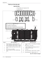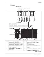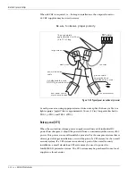
Intelli-FLEX II processor settings
5 - 40 • • • Intelli-FLEX II product guide
JP-4 LED power
•
Remove JP-4 to prevent LED indicators on the processor board from lighting,
otherwise leave the shunt in place.
JP-5 Power Fail Jumper
•
Remove JP-5 to prevent the Power fail supervision alarm, otherwise leave the
shunt in place.
JP-6 Option Jumper
•
Reserved for future use. The shunt must remain installed on JP-6.
Alarm and supervision relays
The dual zone Intelli-FLEX II processors may be connected to many types of alarm
monitoring/report systems using the two form C, single-pole, double-throw
latching type, output relays for each zone.
•
The NC (normally closed) contacts of the alarm relays will close when an
alarm condition occurs. The NO (normally open) contacts will open when an
alarm condition occurs.
•
The NC (normally closed) contacts of the supervision relay will close when a
supervision condition occurs. The NO (normally open) contacts will open
when a supervision condition occurs.
•
If the processor looses power, the NC (normally closed) contacts of the alarm
and supervision relays will close, and the NO (normally open) contacts will
open.
The relays have an associated LED, red for intrusion, and amber for supervision
alarm.
Wiring to alarm and supervision relays
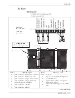
The Intelli-FLEX II processor uses dry contact relays as alarm and supervision
indicators for each zone. There are four independent relays on each processor -
Alarm 1, Alarm 2, Supervision 1, and Supervision 2.
Each relay has a common connection to either a Normally Open (NO) or
Normally Closed (NC) relay contact. This nomenclature refers to the state the
relay will assume when the alarm is reported, or when there is a power failure
condition. The processor board has the relay and contact designation silk-
screened on the board near the terminal connectors.

