background image

Senstar LM100 Product Guide

Page 21

2

Installation

Installing LM100 luminaires

Generally, a luminaire is attached to every second fence post (6 m spacing). In addition, all of the 
heavier gauge fence posts should have a luminaire (tension posts, corner posts, gate support 
posts). The luminaires should be installed on the side of the fence that faces the perceived threat. 
Luminaires are installed so they are perpendicular to the fence line and plumb, with the head 
facing directly downward. 

Begin with the luminaire AP (the luminaire with a hard-wired connection to the gateway).

At regular fence posts

Tools and equipment

8 mm (5/16 in.) nut driver or socket (cordless drill with 8 mm socket recommended)

ladder or scissor lift suitable for fence height

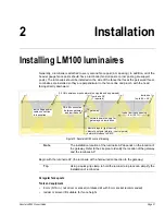
Figure 10: Senstar LM100 concept drawing

Note

The installation location of the luminaire AP depends on the location of 
the gateway. Refer to the site plan to identify the location of the gateway 
and the luminaire AP.

Tip

Using a quick-grip clamp to hold the luminaire in place can simplify the 
installation of luminaires.

2.4 GHz wireless mesh network (encrypted and supervised)

luminaire AP

luminaire

gateway

network power supply for

RS-485 connection

low voltage power

to luminaires

typical luminaire spacing

6 m (20 ft.)

cable connection

(up to 99 + AP)

(1 required)

discrete inputs (light control)
discrete outputs (alarms / control points)

network interface to SMS

gateway and luminaires

 between gateway

 and luminaire AP


Summary of Contents for LM100

Page 1: ...Product Guide Senstar LM100 Intelligent Perimeter Lighting and Sensing Solution E8DA0102 001 Rev D February 14 2020 ...

Page 2: ...standard s Operation is subject to the following two conditions 1 This device may not cause harmful interference and 2 this device must accept any interference received including interference that may cause undesired operation Ce dispositif est conforme aux normes CNR Innovation Sciences et Développement économique Canada applicables aux appareils radio exempts de licence Son fonctionnement est su...

Page 3: ...tion 13 Power source and wiring 13 Power cable protection 13 Auxiliary device output power 13 Power over Ethernet 14 Grounding considerations 14 Alarm monitoring 14 NM Mode alarm reporting 14 Security factors 15 Fence structures 16 Post clamps 16 Flexible fence types 16 Rigid fence types 16 Climb over deterrent hardware 17 Barbed wire 17 Razor ribbon 17 Gates 18 Environment 18 Site Survey 18 Equip...

Page 4: ... connections 42 Network power supply 42 Local power supply 42 Power over Ethernet 42 Backup power 42 Using the wireless gate sensor 43 3 Calibration setup 45 The Universal Configuration Module 45 Senstar LM100 configuration overview 49 Senstar LM100 definitions 50 Senstar LM100 alarm detection 50 Intrusion detection 51 Cut detection 51 Climb detection 51 Luminaire supervision 51 Setting the superv...

Page 5: ...ard 65 Auxiliary Aux inputs 66 Local control mode 66 Remote control mode 66 Remote light activation 66 Input wiring configurations 66 Input configuration procedure 67 Output relays 68 Output relay setup Local control mode 68 Output relay setup Remote control mode 68 Linking relays to zones local control mode 69 System test procedure 69 4 Maintenance 71 Recommended maintenance 71 Preventing weather...

Page 6: ... LM100 system E8DA0103 001 Senstar LM100 quickstart instruction E8DA0303 001 Installing Luminaires E7DA0103 001 Wireless Gate Sensor 00DA0109 001 Network Manager Overview 00DA0209 001 Network Manager Interface 00DA0803 001 Installing the network interface card 00DA1003 002 UltraLink I O 00DA1203 001 Installing the network interface unit 00DA1503 001 Installing I O cards ...

Page 7: ...n RS 485 half duplex connection between the RF based luminaires and the gateway The Senstar LM100 luminaires are typically mounted on the perimeter fence but can also be mounted on walls or other surfaces The luminaires communicate over a proprietary wireless mesh network transmitting status information and receiving control point commands from the gateway via the hard wired connection to the lumi...

Page 8: ...nately the I O points can be controlled remotely by a security management system SMS In this case the outputs are used to activate auxiliary equipment and the inputs are used to communicate the status of auxiliary devices to the SMS The outputs are individually configurable and can source up to 100 mA to power auxiliary equipment The inputs to the gateway must be voltage free The Senstar LM100 sup...

Page 9: ...w an Event Count and an Alarm Window There is also a Target Filter which can be used to screen out some sources of environmental and mechanical noise Each luminaire is supervised to ensure operation and communication and protect against tampering and the removal of the device The luminaire s lighting properties are also setup globally and are assigned on a zone by zone basis This includes brightne...

Page 10: ...he data and triggers an alarm when the received signals meet the criteria for a valid intrusion The luminaire AP includes a 3 m 10 ft 4 conductor cable to make the power and data connection to the gateway The luminaire AP can be installed up to 100 m 328 ft away from the gateway by splicing in a suitable length of data power cable To use the extended cable length requires a minimum 24 VDC power su...
Page 11: ...ateway to a PC running the Silver Network Manager wireless gate sensor receiver card provides wireless security monitoring of up to 4 gates also requires a gate sensor module on each protected gate I O option card either a dry contact input card 4 additional inputs or a relay output card 4 additional outputs Operating Frequency selection IEEE standard 802 11 g stipulates the frequency spectrum use...

Page 12: ...r optic cable requires a network interface card Relay Output Card The relay output card ROC P N 00BA2500 includes four relays to supplement the outputs available on the gateway In local control mode the ROC s outputs signal user selectable alarm and supervision conditions In remote control mode the host security management system operates the ROC s relays as output control points The ROC s outputs...

Page 13: ... based on power supply voltage wire gauge and distance Power cable protection Some Senstar LM100 installations require that the power cables are protected against vandalism and accidental damage There are two recommended methods of providing power cable protection Use armored outdoor and wet location rated power cable Use standard outdoor and wet location rated power cable that is protected inside...

Page 14: ... control mode or Silver Network based alarm reporting networked system remote control mode Each gateway has ten user configurable I O points inputs outputs In standalone mode the outputs are used to signal alarm and supervision conditions For network based gateways alarm data is carried over the network cables and the outputs are available as output control points from the security management syst...

Page 15: ...fence the number of fence posts and the fence post spacing determine the number of luminaires required to provide adequate coverage The maximum recommended spacing for luminaires is 6 m 20 ft The minimum recommended spacing for luminaires is 3 m 10 ft The minimum spacing provides the highest level of security Exceeding the maximum recommended spacing can result in areas with reduced detection sens...

Page 16: ...tion or other objects that can make contact with the fence in windy conditions Post clamps Stainless steel post clamps are included for mounting the gateway and the luminaires The post clamps fit a wide range of post sizes with outside diameters ODs from 4 5 to 13 cm 1 to 5 in The clamps will fit rectangular posts measuring up to 10 cm 4 in per side The recommended luminaire spacing is from 3 to 6...

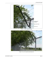
Page 17: ... welded Fasten and secure any loose components Razor ribbon The razor ribbon must be secured so that it does not move in the wind Use bracing wires to secure the coil and to prevent the razor ribbon from separating if it is cut Note The mounting height of the Senstar LM100 luminaires on the fence posts may require adjustment to avoid contact with the climb over deterrent hardware Figure 7 Avoiding...

Page 18: ... on a regular basis The fence must be well maintained to prevent any metal on metal contact caused by the wind Any objects that can make contact with the fence should be removed from the perimeter Heavy vegetation thick weeds brush trees etc should also be kept away from the fence Vegetation should not touch or hang over the fence fabric Site Survey Conduct a site survey to ensure that site condit...

Page 19: ... power supply and the power distribution plan Power cable indicate the type and length of power cables that will be used Alarm communication wiring relay output or network alarm communications indicate the type and length of data cables Wireless Gate Sensor the number of protected gates and the number of WGSs required to cover them Figure 9 Example site plan LM1_AP power cable routing LM2 LM3 LM4 ...

Page 20: ...Equipment layout Page 20 Senstar LM100 Product Guide ...

Page 21: ...in nut driver or socket cordless drill with 8 mm socket recommended ladder or scissor lift suitable for fence height Figure 10 Senstar LM100 concept drawing Note The installation location of the luminaire AP depends on the location of the gateway Refer to the site plan to identify the location of the gateway and the luminaire AP Tip Using a quick grip clamp to hold the luminaire in place can simpl...

Page 22: ...e and fence post to hold the luminaire in place 3 Tighten the clamps so they fit into the slots on the luminaire s bracket and the luminaire is perpendicular to the fence line and plumb to the ground 4 If necessary adjust the position of the luminaire on the fence post and finish tightening the clamps until the luminaire is held securely against the fence 5 Measure the space between the top of the...

Page 23: ...M100 Product Guide Page 23 Figure 13 Luminaire installation example Figure 14 2 4 m 8 ft chain link fence with luminaires min 2 5 cm separation lower the mounting height 2 stainless steel clamps power cable drip loop to increase separation ...

Page 24: ...ire as high on the fence post as possible on the side of the fence that is facing the threat Figure 15 Recommended luminaire spacing 3 to 6 m Figure 16 Luminaire installation on heavy gauge posts cable ties secure power cable to upper tension wire or top rail drip loops 3 m 10 ft spacing single panel 6 m 20 ft spacing double panel regular spacing for standard fence posts reduced spacing for heavy ...

Page 25: ... on rigid fences depends on the type and brand of fence Mount the luminaire as high on the fence post as possible on the side of the fence that is facing the threat Figure 17 Welded mesh fence with luminaires Figure 18 Palisade fence with luminaire back side front side Impasse II high security palisade fence power cable post clamps drip loops ...

Page 26: ...e top of the fence and daisy chained from luminaire to luminaire The power cables pass through a grommet at the bottom of each luminaire and are connected to the luminaire s power wires with nylon insulated closed end crimp connectors Figure 19 Residential palisade fence with luminaires Figure 20 Surface mounting luminaires 1 Hold the luminaire against the surface and mark the holes 2 Drill the ho...

Page 27: ... polarity at each luminaire Note Molex crimp tool p n 64001 0600 is recommended for use with the supplied Molex crimp connectors However the Klein model 1005 or equivalent crimp tool is suitable for this application Note For 14 AWG and above use the supplied Molex crimps p n SD 19160 001 For 12 AWG and larger use Molex crimps p n SD 19XXX 001 The larger Molex crimps are available in kit E8KT0101 2...

Page 28: ...tor back to 15 mm 3 8 in i e 2 negative conductors from power cables and black lead from luminaire 2 positive conductors from power cables and red lead from luminaire 7 Insert the single conductor fully into the open ended connector and verify through the translucent connector before crimping 8 Make the crimp If the crimp tool you are using does not cover the full length of the internal crimp ring...

Page 29: ...y to the fence with UV resistant cable ties P N GH0916 1000 pieces and continue making the power connections Installing the luminaire AP The luminaire AP is usually attached to the same post as the gateway device Mount the luminaire AP in the same manner as the standard luminaires The luminaire AP includes a 3 m 10 ft power and data cable which is connected to the gateway device Figure 29 shows an...

Page 30: ...ired to mount the enclosure on another type of surface is customer supplied Figure 30 illustrates the gateway features and Table 1 includes feature descriptions Figure 32 shows a fence mounted gateway Note The gateway can be installed up to 100 m 328 ft away from the luminaire AP by splicing in a length of power and data cable Protect the splice inside the AP s shaft or in an outdoor rated junctio...

Page 31: ...erimeter can help prevent tampering Item Description Item Description 1 Network interface card mounting hardware X 2 7 T8 I O ports 6 10 2 Activity LEDs DOOR OPEN UCM ACTIVE NETWORK POWER FAIL INTERNAL POWER FAIL RS 485 ACTIVITY BOOT FAIL MEMORY FAIL HEARTBEAT TXA RXA FAULT A TXB RXB FAULT B LED ON condition 8 T5 RS 485 connection to luminaire AP green A white B OR 2 TWO black A 2 TWO white B 9 T6...

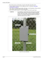
Page 32: ...ecure side of the perimeter away from the fence and razor ribbon Use an 8 mm 5 16 in socket or nut driver to tighten the processor s gear clamps CAUTION For installations in environments which include hot sunny periods Senstar recommends that a sun shield be installed to protect the enclosure from direct sunlight or that the enclosure be installed in a shady area The maximum operating temperature ...

Page 33: ...tainless steel clamp through an upper flange slot around the fence post and back through the second slot 3 Insert the end of the stainless steel clamp into the gear mechanism and tighten the screw 4 Repeat this with the second clamp on the lower flange at the bottom of the enclosure 1 Hold the enclosure against the 2 Drill 4 holes in the mounting surface 3 Using appropriate 6 mm in mounting surfac...

Page 34: ...l dry contact input card provides four additional inputs and the optional relay output card provides four additional relays to supplement the I O on the gateway I O port jumpers Each I O port includes a pair of configuration jumpers which are set according to the intended use of the port For ports that will be configured as outputs and will source power to an external device and for all inputs ins...

Page 35: ...puts I O points defined as inputs are voltage sensing inputs The gateway determines an input s status via an internal reference voltage and the configuration of the contact closures and supervision resistors Figure 37 provides wiring diagrams for auxiliary device inputs In Local control mode the inputs are used to activate luminaire zones When the input goes high the specified luminaire zone is ac...

Page 36: ...ctions Figure 38 and Figure 40 illustrate the gateway wiring connections and the connections to the I O option cards Figure 40 to Figure 45 show the Silver Network wiring options Figure 37 Gateway input wiring examples Note See instruction sheet 00DA1503 for information about installing the optional relay output card and dry contact input card NO inputs unsupervised NO input dual resistor supervis...

Page 37: ...2 to 48 VDC gateway VDC AP VDC AP VDC The AP cable includes 2 twisted pairs of black and white leads The power leads are labeled 1 ONE and the data leads are labeled 2 TWO Connect the black power wire to VDC and connect the white power wire to VDC Connect the black data wire to A side data and connect the white data wire to B side data Verify the labels on the twisted pair before making the connec...

Page 38: ...re 41 Note A network interface card is required on the gateway to enable Silver Network communications Note Use low capacitance shielded twisted pair data cable for RS 422 62 5 125 multi mode fiber optic cable 9 125 single mode fiber optic cable and Category 5 Ethernet cable The maximum separation distances require high quality transmission media and sound installation practices CAUTION Both the g...

Page 39: ...NIC mounting hardware X 2 A side comms B side comms connect the cable shield to on solder side NIC ground connection ground at one end trim back the other end and leave it luminaire AP cable shield ground connection disconnected expansion header T1 T6 gateway power input plugs into T2 on gateway NIC mounting hardware X 2 T2 PoE NIC DC output 12 VDC Ethernet network connection on solder side PoE NI...

Page 40: ... single point grounding connect one end of cable shield trim the other end and leave it disconnected 1 1 2 2 3 3 4 4 5 5 R X B R X B G N D T X B T X B R X A R X A G N D T X A T X A 1 1 2 2 3 3 4 4 5 5 1 2 3 4 5 1 2 3 4 5 1 1 2 2 3 3 4 4 5 5 1 2 3 4 5 1 2 3 4 5 1 2 3 4 5 1 2 3 4 5 R X B R X B G N D T X B T X B R X A R X A G N D T X A T X A R X B R X B G N D T X B T X B R X A R X A G N D T X A T X A...

Page 41: ...st device second device last device Network Interface Unit to Network Manager maximum distance between devices multi mode fiber optic 2 2 km 1 4 miles single mode fiber optic 10 km 6 2 miles maximum 60 devices first device second device last device Network maximum distance third device fourth device fifth device Manager computer security management system computer between device and PoE switch 100...

Page 42: ...NIC can also supply power for the luminaire AP Figure 41 shows a PoE NIC mounted on the gateway CCA Backup power Senstar recommends that the Senstar LM100 system be powered from an uninterruptible power supply UPS Connect AC mains to the UPS and the UPS to the DC power source In this way if AC power is interrupted the LM100 can operate on battery power while AC power is being restored WARNING DO N...

Page 43: ...d transmits alarm data when it detects vibration motion or positional changes A wireless gate sensor receiver GSR mounted on the Senstar LM100 gateway expansion header receives the transmission and passes the alarm data to the gateway Alarm data communications are via the gateway over the Silver Network or by contact closures Note See E7DA0103 Installing the Wireless Gate Sensor for information on...

Page 44: ...Using the wireless gate sensor Page 44 Senstar LM100 Product Guide ...

Page 45: ...ction via Network Manager in the Network Type field select the network to which you are connecting Silver for Senstar LM100 in the Device Type field select the device Senstar LM100 select the connection type i e USB select the connect button to establish the connection in the Network Type field select the network to which you are connecting Silver for gateway to connect via the Silver Network Mana...

Page 46: ...e or wireless gate select a UCM tab to display and configure the associated properties the Event Log contains the 500 most recent Events since the UCM was connected the Diagnostic Status field displays the results of gateway self tests the Head Status field displays information about the luminaires on the wireless mesh network the Auxiliary Status field displays information about the gateway s use...

Page 47: ...ecorded and added to the Event Count When the number of recorded Events reaches the Event Count setting an alarm is declared 1 10 Alarm Window sec Sets the time period after an Event is recorded in which the next Event must occur 1 99 seconds Each time the Event Count is incremented the Alarm Window time is reset and begins to count down from the specified value If a subsequent Event occurs before...

Page 48: ...urrently selected segment into two equal segments Delete button Select the Delete button to merge the currently selected segment with the preceding segment Schedule tab setup automatic lighting controls for the defined luminaire zones time ON schedule starts time OFF schedule ends Zone Level 3 brightness level selections prioritized from lowest to highest i e Level 1 Level 2 force Off SD Card tab ...

Page 49: ...ires alarm detection parameters and threshold see Detection parameter setup on page 58 Event Window Event Count Alarm Window Threshold 7 Setup the luminaires lighting properties and Schedule see Scheduling routine light activation on page 64 Level 1 Light Control brightness setting for scheduled and activated lighting 4th priority Level 2 Light Control brightness setting for scheduled and activate...

Page 50: ...ection for the Senstar LM100 system by evaluating the minute vibrations from the fence to determine whether a disturbance is a valid intrusion or environmental activity The characteristic signal response of a cut event is a sharp spike with a fast rising edge and fast falling edge For a climb event the response includes the fast rising edge caused by the initial contact with the fence which is fol...

Page 51: ...intruder attempts to climb over the fence or lift the fence fabric to crawl under a large number of energy pulses rapidly occur causing the received signal to exceed the Threshold When the signal first exceeds the Threshold the Event Count is incremented and the Alarm Window time count begins Typically during a climb or lift type intrusion the received signal remains above the Threshold as a resul...

Page 52: ...tial setup be done at the gateway location using a direct USB connection to the UCM Connecting the UCM via USB 1 Open the enclosure cover and connect the UCM computer to the gateway via USB T3 2 Start the UCM software the UCM Connect dialog displays see Figure 48 3 Specify the connection details e g Network Type Silver Network Device Type Senstar LM100 Address 1 default address select USB radio bu...

Page 53: ...nown they can be sequenced into a logical order The sequenced heads are then organized into segments and zones Sequencing can be done by one person who starts the recording and then does the location tests or by two people with one monitoring the UCM and the other doing the location tests To determine the physical position of each luminaire and put them into a logical sequence one person goes arou...

Page 54: ...ssigned to alarm zones The Heads Sequence field also includes segment and zone number assignments once the segments and zones are defined in the segment setting window on the Config tab Compiling the Unordered Heads list 1 Establish a UCM connection to the gateway USB or NM 2 On the Config tab select the Sequence button 3 Select the Record button below the Unordered Heads field and wait for the LM...

Page 55: ...tton below the Ordered Heads table and proceed to the designated first luminaire usually the luminaire AP 2 Strike the shaft of the first luminaire firmly once The luminaire will flash twice pause and then flash three times The number one and the luminaire s 5 digit Id are displayed at the top of the Ordered Heads list 3 Proceed to the second luminaire and strike the shaft of the second luminaire ...

Page 56: ...s button to save the changes 6 Save the UCM file and download the configuration changes to the LM100 gateway Senstar LM100 calibration When calibrating the Senstar LM100 for the first time begin with the detection parameters in the default settings The Sensitivity Profile A Sensitivity Profile should be recorded for the full length of the protected fence The Sensitivity Profile records each lumina...

Page 57: ...sible Repeat this process from the end of the protected fence back to the start point 1 Establish a connection between the UCM and the gateway 2 On the Config tab select the Profile button 3 Verify that the All radio button is selected and then select the Record button to begin recording the Sensitivity Profile 4 At the luminaire AP begin dragging the screwdriver along the fence fabric Lift the sc...

Page 58: ...tar LM100 detection parameters are available on the Lights sub panel and include the Event Window the Event Count and the Alarm Window The Segments Zones and Thresholds are setup on the Zones sub panel The Threshold is set independently for each defined luminaire segment Each LM100 installation includes many site specific factors Therefore the system should be calibrated to meet the site s detecti...

Page 59: ... the alarm zone layouts for display and control and routine lighting Once the segments and zones are setup you adjust the Threshold independently for each defined segment to match the sensors response to the fence conditions and to increase or decrease the detection sensitivity for that segment Note The LM100 UCM Config tab includes 2 indicate buttons to assist in identifying specific segments and...

Page 60: ...ly selected segment 2 Left click the boundary line and drag the boundary to the appropriate point in the segment setting window or use the Head field spin control to enter the number of the luminaire that represents the start of the currently selected segment 3 Use the Zone spin control to assign the segment to an alarm zone label the zone according to the site plan multiple segments can be assign...

Page 61: ...ach of the defined segments Thresholds can be adjusted for any high risk or low threat areas as well as any areas that may be subject to a higher nuisance alarm rate NAR such as an open stretch of fence that is regularly exposed to strong winds The Threshold can also be used to disable alarm detection in a segment by setting the Threshold to the maximum value of 254 Reducing the Threshold in high ...

Page 62: ...configuration data to the gateway Figure 57 illustrates a Segment setting window for a Senstar LM100 system which has been split into 6 segments and 5 zones Segments 1 2 and 5 Zones 1 2 and 4 use the overall Threshold setting Segment 4 and segment 6 Zone 3 are considered high threat areas and the Threshold has been set to a lower value to increase the detection sensitivity in zone 3 Segment 3 repr...

Page 63: ...imply needs to climb on the fence for a period that exceeds the Event Window time setting X the Event Count setting e g 1 second X 3 Events 3 seconds If climbing on the fence is not possible dragging a screwdriver across the surface of the fence can be used as a climb simulation Place the blade of a screwdriver against the fence fabric and drag the screwdriver back and forth across the fence panel...

Page 64: ...e time at which the schedule will begin On 4 Set the time at which the schedule will end Off 5 Choose the days of the week on which the schedule will be active 6 Choose the luminaire zone that will follow the schedule select All if the schedule applies to all installed luminaires 7 Select the brightness Level for the schedule Level 1 Level 2 or force Off 8 Save the UCM file and download the config...

Page 65: ...9 Aux Cfig tab use the radio buttons to specify each port s function intrusion alarm outputs are assigned on the Config tab any head has a supervision condition any head has lost communication with gateway any head is reporting a fault condition the gateway s enclosure door is open the gateway has an input power fault the gateway has a hardware fault changes state to indicate the gateway has lost ...

Page 66: ...es The gateway reports any change of an input s state to the SMS via the Silver Network Manager Remote light activation In both local control mode and remote control mode the Senstar LM100 can be configured to have specific luminaires activated from remote locations In local control mode a simple on off switch in a central control room can be connected to an Aux input on the gateway When the switc...

Page 67: ...brightness for the activated zone 11 Repeat this procedure for each designated input 12 Save the UCM configuration file and download the configuration changes to the gateway Input option UCM selection Alarm relay Supervision R1 R2 unsupervised NO single resistor supervision NO cut 5 1 k dual resistor supervision NO cut short 4 3 k 820 unsupervised NC single resistor supervision NC short 5 1 k dual...

Page 68: ...quipment as output control points e g to activate lights doors sirens CCTV equipment etc The relays are configured to respond to commands from the host computer Configure the relays as latching ON by command OFF by command or in flash mode ON OFF ON OFF etc by command OFF by command or in pulse mode ON for a period then OFF For flash and pulse modes the ON OFF time duration is configurable 1 Use t...

Page 69: ... 5 Save the UCM configuration file and download the configuration changes to the gateway System test procedure Once the system is setup and calibrated conduct a series of tests to verify detection Run a UCM Response plot during the testing Network based gateways can be tested over the network to verify network communications Cut detection Use the tap test or weave a piece of scrap fence wire tight...

Page 70: ...cal control mode the Aux inputs activate luminaire zones In this case activate the input and verify that the specified luminaire zone activates in response For Remote control mode the Aux inputs serve as auxiliary device inputs to the host Security Management System In this case activate the connected device and verify the status change is reported by the host SMS Repeat for each configured input ...

Page 71: ...de and above the fence is cut back and cannot make contact with the fence or the luminaires and there is no debris or loose material close to the fence there are no loose clamps each luminaire is held tightly against the fence post power cables are neatly installed and are fastened securely there is no corrosion or moisture inside the gateway enclosure the ground connection is tight there are no v...

Page 72: ... UCM to the gateway review the processor history and adjust the Threshold to mitigate the effects of the weather To determine if there are any loose fittings or parts of the fence that can cause nuisance alarms in windy weather grip a fence panel in the middle and push and pull on the fence with an increasing motion Run a response plot to record the shake tests and listen for any metal on metal co...

Page 73: ...f required reinstall the option cards on the expansion header 4 Reconnect the tamper switch connector 5 Reinstall the removable terminal blocks 6 Apply power to the gateway connect the UCM and download the replaced gateway s configuration file to the replacement gateway 7 Retest the protected fence and recalibrate if required Updating the Senstar LM100 Firmware To update the Senstar LM100 device f...

Page 74: ...way Heads for luminaires GSM Base for wireless gate sensor receiver GSM Sensor for gate sensor module 3 Select the Use Current Active configuration after programming unit radio button then select the Browse button 4 Navigate to the location of the firmware file and select the appropriate XDU file If you select an incorrect XDU file the UCM will not allow the installation 5 Select the Program butto...

Page 75: ... resistant cable ties GH0916 UV resistant polypropylene cable ties for power cable installation 1000 piece bag power cable 10 2 GW0337 10 150 m 492 ft reel of 10 AWG 2 conductor outdoor and wet location rated low voltage power cable power cable 14 2 GW0337 14 150 m 492 ft reel of 14 AWG 2 conductor outdoor and wet location rated low voltage power cable 10 AWG power cable crimps E8KT0101 closed end...

Page 76: ...tic communications Network Interface Card RS 422 00BA2000 Network interface card for copper wire communications Network Interface Card single mode fiber 00BA2101 Network interface card for single mode fiber optic communications Network Interface Card Ethernet PoE 00BA2200 Power over Ethernet network interface card for Ethernet communications Configuration and Network software UCM cable GE0444 UCM ...

Page 77: ... 11 4 mm 0 17 to 0 45 in Probability of detection 95 with a 95 confidence factor for cutting the fence lifting the fence fabric or climbing over the fence unaided based on a high quality chain link fence and following manufacturers installation and calibration recommendations Maximum recommended fence coverage per system 600 m 1970 ft max recommended fence length 100 luminaires including luminaire...

Page 78: ...gurable relay response LED indicators power one dual color LED per relay UCM connected Enclosure door open diagnostic activity Supervision mechanical enclosure tamper switch luminaires gateway operation Temperature 40º to 70ºC 40º to 158º F as measured inside the enclosure Relative humidity 0 to 100 luminaire luminaire AP Controls light intensity scheduled lighting routine lighting schedule alarm ...

Reviews: