Mounting
2 - 8 • • • MPS-4100 product guide
For alarm data communication wiring, the cable should be individually shielded,
twisted, with overall foil and braided shield in a High Density Polyethylene outer
jacketing. The number of conductors required depends on your alarm reporting
requirements. Contact Senstar for data cable availability.
Wire must be rated for outdoor direct burial use in wet
conditions.
Mounting procedure
Mount MPS-4100 microwaves 76 cm (30 in.) above ground to
the center of the unit.
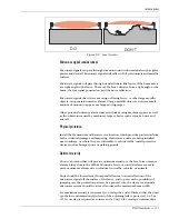
1. Attach the post mounting bracket to an 8, 9, or 10 cm (3, 3½, or 4-inch) OD
post. The bracket should be 76 cm (30 in.) above ground to center, with the
two slotted holes toward the rear (away from the zone). Tighten the bracket
firmly into place. (See Figure 2-5 and Figure 2-6.)
2. Insert the supplied mounting hardware (machine screw, lock washer, flat
washer) through the slotted holes in the post mount bracket, and screw them
into the bracket on the side of the MPS-4100 (see Figure 2-6).
3. Remove the cover by loosening the 4 captive screws. Pull the cover away and
allow it to hang by the strain relief.
4. Attach 2 cm (¾ in.) diameter watertight flex conduit between the junction
box at the base of the post and the conduit connector on the rear cover of the
microwave unit.
Be sure the conduit outlet on the back of the unit faces down to
allow water to drain away from the connector.
5. Route the wiring through the flex conduit. Pull enough wire to create a
service loop and to allow for the removal of the cover.
6. Using a suitable ground wire, connect a properly installed ground rod to the
¼ X 20 ground screw on the outside bottom of the enclosure (see Figure 2-6).
WIRE GAUGE
(STRANDED COPPER BARE)
VOLTAGE DROP PER 150 m (500 FT.)
TRANSMITTER OR RECEIVER
VOLTAGE DROP PER 150 m (500 FT.)
TRANSMITTER and RECEIVER
#18 AWG (1.05 mm dia.)
#20 AWG (0.82 mm dia.)
#22 AWG (0.66 mm dia.)
#24 AWG (0.54 mm dia.)
#26 AWG (0.41 mm dia.)
0.2 V
0.3 V
0.5 V
0.8 V
1.2 V
0.4 V (0.8 V*)
0.4 V (0.8 V*)
1.0 V (2.0 V*)
1.6 V (3.2 V*)
2.4 V (4.8 V*)
* Voltage drop with Communication Interface Card installed in Receiver.
Table 2-1 Voltage drop vs. wire gauge

