MPS-4100 Receiver
1 - 6 • • • MPS-4100 product guide
MPS-4100 Receiver
The Model MPS-4100 Receiver consists of two major sub-assemblies, the antenna
assembly and the Receiver circuit board. The antenna assembly is a planar or
linear patch array antenna, with a signal preamplifier and Schottky diode detector
located on the rear side. The antenna captures the microwave energy from the
Transmitter. The microwave signal is first preamplified. This compensates for
attenuation of the incoming signal due to environmental factors such as objects in
the pattern or rain. The Schottky diode detector converts the modulated X-band
energy into an audio frequency signal for processing by the Receiver circuit
board. The antenna assembly attaches to the Receiver circuit board by means of
stand-off fasteners so that the two form a single removable assembly.
The Receiver circuit board includes the processing circuitry that generates an
alarm when sufficient changes in the microwave signal are detected. The
modulation frequency is set to match that of the Transmitter via jumpers located
on the circuit board. The gain of the signal amplifier may be adjusted by means of
a Sensitivity potentiometer. The higher the sensitivity setting, the lower the
change in received signal required to generate an alarm. The signal bandwidth,
affecting the response to fast moving targets, may be set to Fast or Slow via a
jumper on the Receiver circuit board.
The Receiver circuit board includes three LED’s for indicating Alarm, Wrong
Channel, and Jam conditions. The Alarm LED indicates an alarm condition. The
Wrong Channel LED indicates that the modulation frequency of the Receiver does
not match that of the Transmitter. The Jam LED indicates that the Receiver is
picking up two microwave signals at the same modulation frequency, signifying
interference between two microwave units. A Jam condition can be set to trigger
an alarm output via a switch on the Receiver.
The Receiver circuit board includes header P1 for connecting a Communications
Interface Card. This enables communication via the Silver Network, the StarNeT
1000 system or the MX-5000 Series Control Center. The Receiver also includes a
pre-amp that outputs audio signals enabling audio assessment of activity within
the microwave field.
The Receiver includes an alignment aid consisting of a series of ten LED’s that
indicate the received signal strength. Test points are available for voltmeter
verification of the microwave’s alignment. There is also a local audio output for
connecting a 3 mm (1/8 in.) headphone jack, which is used for audio assessment
of microwave field disturbances. In addition, several operating parameters are
selectable via jumpers and DIP-switches on the Receiver circuit board.
Coverage pattern
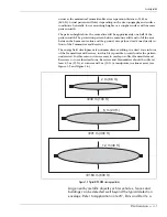
The antenna creates a microwave energy field at an approximate 13º angle
(horizontal polarization app. 13º; vertical polarization app. 11º). This results in a
typical maximum width protection pattern of 12 m (40 feet) at a mounting height
of 76 cm (2.5 feet) above level earth (see Figure 1-4). The maximum beam width


