Installation planning
2 - 4 • • • MPS-4100 product guide
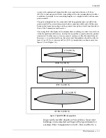
points. The side-by-side offset of overlapping in-line links should be
approximately 46 cm (18 in.), measured from the center of each unit.
At each point of overlap either two Transmitters or two
Receivers should be installed. This arrangement prevents an
adjacent Transmitter and Receiver from establishing an
unwanted link across the short overlap distance, which could
result in a Jam or Wrong Channel indication at the Receiver
(see Figure 2-3).
Wiring and configuration
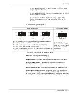
The MPS-4100 may be configured for Relay Output or for Network
Communications depending on the model installed. All wiring connections are
made on removable terminal blocks, which facilitates maintenance and service
activities.
The MPS-4100 provides dry relay outputs for alarm and tamper that can be wired
to virtually any alarm sensor with auxiliary inputs, including the OmniTrax
®
processor, XField
®
processor, Perimitrax
®
Sensor Module, Intelli-FLEX™
processor, PLC transponder, etc. The MPS-4100 can report alarm data via the
Silver Network to the Sentient
TM
security management system, or to a Perimitrax
or Intelli-FLEX Central Controller, Senstar
®
100, StarNeT 1000
TM
, FPS-3
Central
Controller, MX-5000 Command and Control Center, etc. The Silver Network can
also communicate with a third party alarm display and control system via the
Network Alarm Interface.
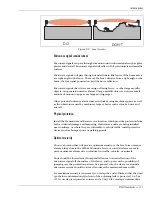
Figure 2-3 Perimeter layout (100% coverage)
CAUTION: DO NOT apply power until all wiring connections have been made.
Tx1
Tx2
Rx1
Rx2
Rx3
Tx3
Tx4
Rx4
Rx5
Tx5
Tx6
Rx6
9 m
intermediate
overlap
4.5 m corner
offset
46 cm offset
perimeter fence
Corner offsets plus intermediate overlaps and offsets provide 100% coverage around the
inside of the perimeter fence.

