MX-7000 Installation and operation manual
P a g e
| 11
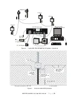
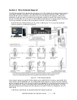
Run the sensor cable from each FPS processor as shown in Figures 7 and 9.
NOTE: Your installation may utilize either standard MEX sensor cable or Helisensor. Observe
special requirements for each type of sensor cable.
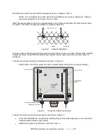
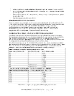
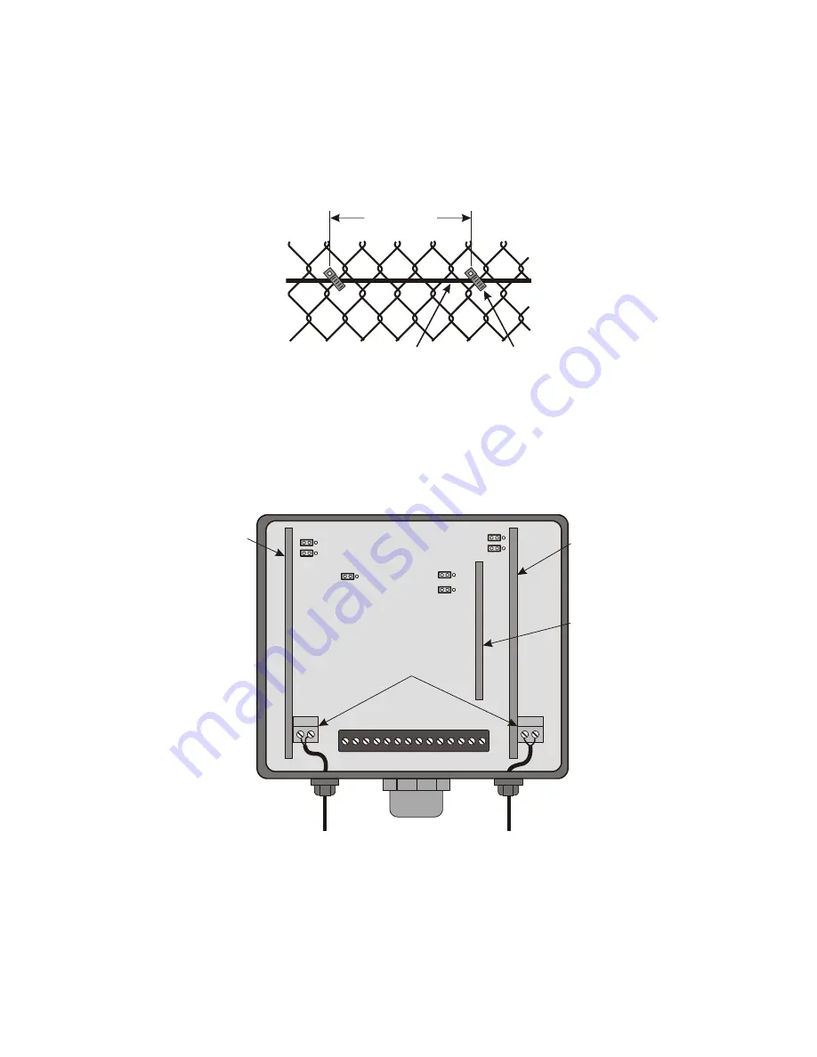
Attach the sensor cable to the fence at approximate 12-inch intervals with black UV cable ties as shown
in Figure 8. Use ONLY the approved black UV-protected cable ties.
Figure 8
Cable tie installation
Provide a loop at each fence post and sensitivity loops at each corner or end post. Create cable overlaps
at adjacent zones. Install TSK termination boxes at each sensor cable end-of-line and any splices, if
necessary.
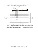
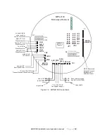
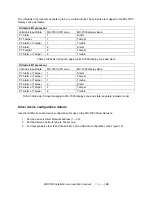
Connect each sensor cable to the processor as shown in Figure 9.
NOTE: Refer to the FPS system manual for detailed setup information and jumper settings.
Figure 9
Transducer Cable Connections
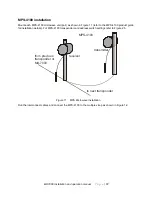
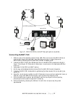
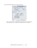
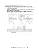
Connect the control wiring to each processor as shown in Figure 10.
•
Verify that all shields are connected as indicated. Keep the shields separate, do not connect the
individual cable shields to one another.
•
Install a short jumper wire between terminals 1 and 3.
cable
cable tie
30 cm (12 in.)
C
E
N
T
E
R
S
H
IE
L
D
1 2
removable
terminal
blocks
zone 1 PCB
zone 2 PCB
transponder
PCB
C
E
N
T
E
R
S
H
IE
L
D
1 2
JP1
JP2
JP3
JP4
JP5
JP6
JP7
turn compression glands
clockwise to close


