MX-7000 Installation and operation manual
P a g e
| 19
•
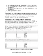
RS-422 copper wire shielded twisted pair data cable (2 pairs per channel) - 1.2 km (0.75 mi.)
•
62.5/125 multi-mode fiber optic cable (820 nm) - 2.2 km (1.4 mi.) - 2 fibers per Channel - optical
power budget 8 dB
•
9/125 single-mode fiber optic cable (1310 nm) - 10 km (6.2 mi.) - 2 fibers per Channel - optical
power budget 8 dB
•
FlexZone sensor cable - 600 m (1,970 ft.)
Silver Network device documentation
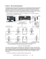
Detailed installation, setup and operation instructions are included in each devices Product Guide. The
Product Guides also include communication options and powering requirements. Silver Network devices
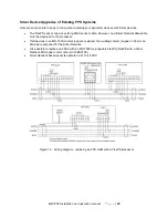
are typically powered from a centrally located 48 VDC Network Power supply. Alarm data
communications can be over RS-422 wiring or fiber optic cable (single-mode or multi-mode).
The MX-7000 supports only the Silver Network loop configuration. Go to the Senstar website
(www.senstar.com) to request copies of the Silver device Product Guides.
Configuring Silver Network devices for MX-7000 implementation
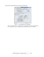
Silver Network devices are configured via the Universal Configuration Module (UCM). The UCM is a
Windows based software application, which communicates with the Silver devices locally via USB. The
UCM can also communicate with the Silver based devices over the network if the MX-7000 is
disconnected (requires Silver Network Manager software). If only local USB connections are anticipated,
the configuration should be performed before each device is field installed.
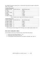
For all Silver device types except the UltraLink I/O, the processor zone and device states are enabled
using the remote configuration relay setup (also known as UltraLink I/O Network Manager mode). Table 3
shows how the remote configuration relays map to the MX-7000 display zones and states for each
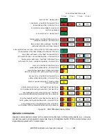
processor. The MX-7000 reports the device and zone states as indicated in Figure 18.
FlexPS, FlexZone-4, Senstar LM100, UltraWave (zone 1 only)
Relay to set in Remote Cfig
MX-7000 XPO zone
MX-7000 display state
P1
1
Alarm
P2
1
Tamper
P3
1
Trouble
1-1
2
Alarm
1-2
2
Tamper
1-3
2
Trouble
P4
All XPO zones*
Tamper
P5
All XPO zones*
Trouble
* All zones defined for that processor in the MX-7000 display zones database.
FlexZone-4 and Senstar LM100 have 4 zone capability (Alarm Zones 3 & 4)
1-9
3
Alarm
1-10
3
Tamper
1-11
3
Trouble
1-17
4
Alarm
1-18
4
Tamper
1-19
4
Trouble
Table 3 Remote Cfig relay mapping to MX-7000 display zone and state

