MX-7000 Installation and operation manual
P a g e
| 20
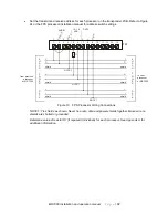
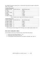
The UltraLink I/O processor accepts up to 6 dry contact inputs. These inputs are mapped to the MX-7000
display zones as follows:
UltraLink I/O processor
UltraLink Input/State
MX-7000 XPO zone
MX-7000 display state
P1 Alarm
1
Alarm
P1 Tamper
1
Tamper
P3 Alarm or Tamper
1
Trouble
P5 Alarm
2
Alarm
P5 Tamper
2
Tamper
P7 Alarm or Tamper
2
Trouble
Table 4 UltraLink I/O input mapping to MX-7000 display zone and state
UltraLink I/O processor
UltraLink Input/State
MX-7000 XPO zone
MX-7000 display state
P1 Alarm or Tamper
1
Alarm
P2 Alarm or Tamper
1
Tamper
P3 Alarm or Tamper
1
Trouble
P5 Alarm or Tamper
2
Alarm
P6 Alarm or Tamper
2
Tamper
P7 Alarm or Tamper
2
Trouble
Table 5 UltraLink I/O input mapping to MX-7000 display zone and state (separate tampers mode)
Silver device configuration details
Use the UCM to set each device configuration for use on the MX-7000 Silver Network:
1.
Set the device’s Silver Network address (1 – 30).
2.
Set the device’s network type to Silver Loop.
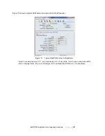
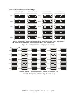
3. For transponders other than UltraLink I/O, set the Remote configuration (see Figure 15).

