MX-7000 Installation and operation manual
P a g e
| 43
The voltage drop between the farthest cable distance XPO and next XPO (XPO2) is calculated using a
current of 30 mA through the resistance of the cable (Rc). If there is 2,000 ft. (Dc1) of power wires
between the two processors then:
Vc1 = 30 mA x 14 x Dc1
Vc1 = 0.03 x 14 x 2
Vc1 = 0.84 V
Therefore, the input voltage at XPO2 equals the voltage at XPO1 (12 V) + Vc1 (0.84 V) = 12.84 V
Shorter distances will result in a lower voltage drop. This process is repeated to calculate the voltage at
each processor. Once known, the value of a voltage dropping resistor (Rd) connected between processor
power input TB 1-5 and the field power wire can be determined that will reduce the processor input
voltage to a value between 12 and 16 volts.
Selecting the voltage dropping resistor (Rd)
The value of the voltage dropping resistor (Rd) is determined as follows:
If the voltage at a processor is between 12 and 16 volts, no resistor is required.
If the voltage at a processor is between 16 and 18 volts, a 100 Ohm 1/4w resistor is required.
If the voltage at a processor is between 18 and 21 volts, a 200 Ohm 1/4w resistor is required.
If the voltage at a processor is between 21 and 24 volts, a 300 Ohm 1/2w resistor is required
Designing an MX-7000 power distribution network
The following example shows the power distribution of a typical maximum sector length system with 5
FPS processors (10 zones), spaced 2,000 cable feet apart. The MX-7000 is located 1,000 cable feet
away from the closest processor.
The design for this system will establish the following:
1. The voltage at the power input to each processor (TB 1-5 + with respect to TB 1-6 -).
2. The value of the voltage dropping resistor (Rd) if required.
3. The voltage setting required at the output of the MX-7000 loop card.
The design routine is as follows:
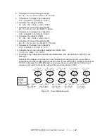
1. Draw the equivalent resistance network (see Figure 30)
2. Set V1 = 12 volts
3. Calculate Vc1 (voltage drop between XPO 1 and XPO 2) with 30 mA (current flowing between
XPO1 and XPO2) through 28 ohms (resistance of Cable #1 between XPO 1 and XPO 2)
Vc1 = (I1) (Rc1) = (0.03) (28) = 0.84V
4. Calculate V2 (voltage at XPO2)
V2 = V1+Vc1 = 12 + 0.84 = 12.84 V
5. Calculate lc2 (current through cable #2)
lc2 = I1 + I2 = 0.03 + 0.03 = 60mA
6. Calculate Vc2 (voltage drop in cable #2)
Vc2 = (lc2) (Rc2) = (0.06) (28) = 1.68V
7. Calculate V3 (voltage at XPO3)
V3 = V2 + Vc2 = 12.84 + 1.68 = 14.52

