background image

MX-7000 Installation and operation manual 

P a g e

 | 36 

12.  For EDAPT zones change the EDAPT count if desired and set separate tampers for processors 

so configured. Silver Network devices do not have EDAPT capability. 

13.  Select Next Zone and continue until all zones have been reviewed and configured, as required.  
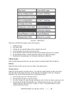
Port configuration 

Use the Port configuration function to setup the MX-7000 serial ports and parallel printer port. 

1.  Select Port: and choose the port that you are configuring (COM1, COM2, COM3, LPT). 

2. 

Select Function: and specify the connected device (not used, host interface, weather, video 
switcher, printer). 
 

NOTE: The Baud rate, Parity, Data bits and Stop bits are fixed for MX-7000 communications. 
 

3.  Status messages: Off-no status messages, On-status messages sent when state changes, or 

Automatic-a zone status message is sent every second.  

4.  Host Mode: Off-no host control, ON-host control only (no local operator control), Both-host and 

local operator control. 

5.  Select Next port and continue to setup the MX-7000 communication ports. 

System Settings 

The System Settings function allows you to specify general operating characteristics for the MX-7000. 

1.  Select ARKS fail alert (enabled or disabled). 

2.  Select Categories (enabled or disabled). 

3.  Select Auto acknowledge alarms (yes or no). Auto acknowledge and reset alarms when clear. 

4.  Select Auto rst tampers (yes or no). Auto reset tampers when clear.  

5.  Select Auto rst comfails (yes or no). Auto reset comm fails when clear. 

6.  Select Manu rst testfails (yes or no). Allow operator to manually reset test failures. Otherwise the 

test fail is only resettable by a successful re-test. 

7.  Auto reset delay: time in seconds after alarm before auto-ACK/RST is performed.  

8.  Select Test alarms to relays (yes or no). Test alarms activation of standard relays. 

9.  Set IP addr: Set the IP address of this MX-7000. 

10.  Set IP mask: Specify the subnet mask for the MX IP network. 

11.  Set IP gate: Specify the IP address for the gateway for the MX IP network. 

12.  Select Alert tone: (enabled or disabled). 

13.  Select Remote Map Interface (RMI): (enabled or disabled). 

Other Setup functions 

Set password access 

The Set password access function allows the system administrator to specify up to five distinct levels of 
user access to MX-7000 system functions. 

1.  Beginning with Level 1, select Password: 

2.  Enter the old password, enter the new password, and then confirm the new password. 

3.  Select Access: and then specify the functions that this Level may access (touch the functions to 

include them for this access level). Select Done to return to the Set password access menu. 

4.  Select Next level and repeat the process for the next level of password access. 

5.  Continue this process until all required levels of password access have been specified. 

Summary of Contents for MX-7000 Series

Page 1: ...MX 7000 Series Command and Control Center Installation Operation Manual J9DA0802 001 Rev B July 13 2018 ...

Page 2: ...guide has been prepared by Senstar Corporation to the best of its ability Senstar Corporation is not responsible for any damage or accidents that may occur due to errors or omissions in this guide Senstar Corporation is not liable for any damages or incidental consequences arising from the use of or the inability to use the software and equipment described in this guide Senstar Corporation is not ...

Page 3: ...rk devices for MX 7000 implementation 19 Silver device configuration details 20 Silver Device Upgrades of Existing FPS Systems 22 Section 5 Operator Interface 23 Description 23 Zone Status display 23 Operator commands 24 Command Line 25 ACK RST Acknowledge and Reset 25 Audio 26 Test 26 Access 26 Setup 26 Section 6 Installation 27 Power connections 27 Transformer setup 120 V 220 VAC input 28 Backup...

Page 4: ...ta 37 EDAPT Settings 37 Acknowledge all 38 Load Software 38 Return to control 38 Section 8 Network Connections 39 MX configuration using a Web browser over an IP connection 39 Software Upgrades over an IP connection using DCUFinder jar 40 Upgrading the MX software 40 Software Upgrades over an IP connection using a web browser 41 Section 9 Appendix A 42 Multiplex copper loop power distribution calc...

Page 5: ...0 supports 60 see Figure 1 Regardless of which model is selected the MX series supports up to 30 Silver devices via 2 of its 4 USB ports Figure 1 MX 7000 Front Panel single screen model System Description Alarms generated by field mounted sensors are processed and displayed by the MX 7000 while providing operator control of the security system The MX 7000 main board is bus architecture based meani...

Page 6: ... GND GND RESET ETHERNET RTC BATTERY USB BACK USB FRONT DISPLAYS LOCAL BUS PRINTER J3 EIA 232 3 COM 3 EIA 232 2 COM 2 EIA 232 1 COM 1 R L SDcard P7 LOOP 3 P6 LOOP 2 P5 LOOP 1 P4 P6 P5 P4 P10 P17 P18 P16 P15 J4 J5 P13 P12 processor OK D6 P9 POWER P9 D12 D17 Status ARKS P2 LED1 LINK 100 DUP COL Ethernet USB link D7 D4 D3 D2 D1 D24 LED2 D23 ...

Page 7: ...d LED descriptions Figure 4 Audio card TB1 Pins 1 2 Audio input 1 TB1 Pins 3 4 Audio input 2 TB1 Pins 5 6 Audio input 3 TB1 Pins 7 8 External speaker connection GAIN 1 use GAIN 1 to adjust the input signal volume for audio input 1 GAIN 2 use GAIN 2 to adjust the input signal volume for audio input 2 GAIN 3 use GAIN 3 to adjust the input signal volume for audio input 3 TFA Use TFA to adjust the fre...

Page 8: ...r systems and with third party security devices Refer to the manufacturers documentation when installing and setting up the connected equipment Btry NO Btry JP1 15V 150 mA Battery GND Transformer TB1 POWER D11 J1 place jumper on Btry position to enable low battery alarm place jumper on NO Btry position to disable low battery alarm ...

Page 9: ... device locations all FPS processors and all MPS 4100 microwave locations Use the approved multiconductor shielded cable or equivalent for connecting the MX 7000 to the FPS and MPS units The Senstar Interconnect Cable p n SP3922 TUV is a three pair 18 AWG individually shielded twisted pair cable with overall foil shield braided shield and high density polyethylene jacket The interconnect wiring sh...

Page 10: ... 7000 rear panel AC power transformer 24 V battery pack ARI MMI RMI earth ground FPS 2 2 FPS 2 2 Psycon security management system FPS 2 2 Unistrut type mounting watertight compression fittings connect earth ground to enclosure ground bolt space cable ties approximately 12 in apart from previous processor or MX 7000 use an approved earth ground rod to next processor ...

Page 11: ... overlaps at adjacent zones Install TSK termination boxes at each sensor cable end of line and any splices if necessary Connect each sensor cable to the processor as shown in Figure 9 NOTE Refer to the FPS system manual for detailed setup information and jumper settings Figure 9 Transducer Cable Connections Connect the control wiring to each processor as shown in Figure 10 Verify that all shields ...

Page 12: ...audio data and power shields together Make sure no shields are shorted or grounded Determine value of resistor R1 if required individually for each processor See Appendix A for additional information 1 2 3 4 5 6 7 8 10 11 12 13 14 9 AUDIO 12 16 VDC DATA 1 2 c o m m o n _ s h i e l d _ R1 s h i e l d 1 C shield _ shield _ shield A U D I O P O W E R D A T A from previous processor or MX 7000 to next...

Page 13: ... the MPS 4100 product guide for installation details For MPS 4100 transponder card address switch settings refer to Figure 25 Figure 11 MPS Microwave Installation Run the interconnect cables and connect the MPS 4100 to the multiplex loop as shown in Figure 12 MPS 4100 receiver transmitter from previous transponder or MX 7000 to next transponder ...

Page 14: ...e shield JP1 JP2 S1 1 2 3 4 5 6 ON OFF 1 2 3 4 5 6 ON OFF 12 to 24 VDC O P to Transmitter and Slave Receiver 12 to 24 VDC I P from power supply MPS 4100 Microwave Receiver Alarm I P from Slave Receiver Tamper I P from Slave Receiver Audio I P from Slave Receiver audio shield to common MX 7000 network transponder card installed on PI XPNDR CONN P1 Data communication bus I O to MX 7000 tape shield c...

Page 15: ...rocessor supply voltage is below 12 VDC the MX 7000 copper loop card output voltage at TB1 pins 4 5 see Figure 20 can be increased by trimming R40 on the loop card If the end of line processor supply voltage cannot be brought to 12 VDC without exceeding 16 VDC at the first in line processor then voltage dropping supply resistors must be added as described in appendix A 5 Complete the MX 7000 confi...

Page 16: ...rved Ensure the MX 7000 is connected to a proper electrical ground Install ground rods and proper grounding at outdoor device locations all FPS processors and all MPS 4100 microwave locations Terminate fiber according to accepted practices Improper terminations will cause communications errors and degraded performance Installation Figures 13 and 23 show the typical fiber optic interconnection of c...

Page 17: ...iber loop card 3 Apply power to the FPS 5 and SAFT devices 4 Enter setup acknowledge all alarms and perform the MXF 7500 initial configuration 5 Complete the MXF 7500 configuration by performing the steps required for your system see Section 7 6 Adjust the count and gain switches in each FPS processor to provide the required climb and cut detection Align each MPS 4100 microwave pair to optimize th...

Page 18: ...APT processing are not available for devices on the Silver Network Note that the Silver Network devices on loop 4 do not affect loops 1 to 3 or any other peripheral device connections as illustrated in Figure 2 Figure 14 Silver Network diagram Silver Network support requires MX 7000 software version J9SW0500 128 or above plus the MX 7000 Silver Network drivers J9SW0501 001 No additional MX 7000 ha...

Page 19: ...UCM The UCM is a Windows based software application which communicates with the Silver devices locally via USB The UCM can also communicate with the Silver based devices over the network if the MX 7000 is disconnected requires Silver Network Manager software If only local USB connections are anticipated the configuration should be performed before each device is field installed For all Silver devi...

Page 20: ... and state UltraLink I O processor UltraLink Input State MX 7000 XPO zone MX 7000 display state P1 Alarm or Tamper 1 Alarm P2 Alarm or Tamper 1 Tamper P3 Alarm or Tamper 1 Trouble P5 Alarm or Tamper 2 Alarm P6 Alarm or Tamper 2 Tamper P7 Alarm or Tamper 2 Trouble Table 5 UltraLink I O input mapping to MX 7000 display zone and state separate tampers mode Silver device configuration details Use the ...

Page 21: ...pical UCM alarm zone setup for a FlexPS sensor Figure 15 Typical FlexPS Remote Configuration Note To enable the Aux I P 1 you could assign P 1 for its alarm for it to also activate the XPO zone 1 display alarm Or you could assign P 3 to activate the XPO zone 1 trouble alarm ...

Page 22: ... new Silver Network data cable must be deployed to the processor If all devices in an MX 7000 comms loop are replaced the existing comms copper or fiber can likely be repurposed for the Silver Network It is possible to replace an FPS2 with an MX 7000 loop capable FlexPS FlexPS with a Silver Network MX copper comm card p n J9BA0100 Silver Network based sensors operate on 12 to 48 VDC Figure 16 Wiri...

Page 23: ...or other pointing device can also be used as for operator input For systems with more than 20 zones there are two VGA screens The left touchscreen is the command interface and the right display shows the system zones status see Figure 17 For systems with 20 zones or less the single left panel touchscreen is divided into a command interface on the left and a system zone status display on the right ...

Page 24: ...d white 04 04 04 04 tamper alarm acknowledged fast flash red white red white alert tone silenced 04 comm fail acknowledged steady red yellow left 50 red right 50 yellow alert tone silenced 04 04 04 04 04 04 04 04 04 audio selected secure zone left most 20 of zone label is blue the remainder of the label displays the status of the zone zone alarm with audio slow flash slow tone alert left most 20 b...

Page 25: ...For example if an alarm occurs in a zone the operator first enters the zone number on the command screen keypad and then selects the ACK RST function to acknowledge the alarm To reset the alarm the operator enters the zone number and then selects the ACK RST function a second time If alarm categories are enabled the operator must also enter a Category number 1 to 6 to identify the cause of the ala...

Page 26: ...mber in the zone status box to indicate that a test is taking place If the zone passes the test the zone status will return to secure If it fails the test the system declares a zone trouble self test fail alarm in the selected zone Access Use the Access function to disable intrusion alarm reporting for a zone that will be entered for maintenance or another authorized activity Sensor alarms will be...

Page 27: ...tion Desktop mounting is typically used to provide operator access and control Rack mounting is generally used in situations where the MX 7000 is serving as an interface to another display and control system The other system is providing the operator interface to the security system e g Psycon If the MX 7000 will be used as the operator console locate it in a position that Provides operators with ...

Page 28: ...uld have sufficient capacity to power the MX 7000 and the devices it powers for the site specific UPS run time Set the JP1 shunt on the power card Figure 5 based on whether a battery is connected Grounding The MX 7000 requires a low impedance low noise earth ground to ensure proper system operation and transient protection Connect the chassis ground lug on the rear panel of the MX 7000 to an elect...

Page 29: ...ity to power the MX 7000 and its connected sensors to meet the runtime specification site specific chassis ground lug loop 1 audio loop 2 audio loop 3 audio external audio to speaker connect overall cable shield to chassis ground connect audio shield to chassis ground _ _ shield not connected shield 1 2 3 4 5 6 7 8 1 2 3 4 5 data power output shielded multi conductor cable to distributed processor...

Page 30: ...etween a central power supply and the distributed processors Each FPS 2 2 processor requires 30 mA at 12 16 VDC and each FPS 5 and SAFT processor requires approximately 130 mA at 12 24 VDC The central power supply and power cables must be sized accordingly NOTE Use a separate power supply not the MX unit to power fiber optic communicating transponders Figure 24 MX 7000 rear panel MXF 7500 fiber op...

Page 31: ...t the 24 VDC battery pack Apply power to the field processors Bench testing the processor addresses Senstar recommends bench testing each processor on its multiplex loop before field installing the equipment Connect a processor to its designated loop card and then apply power to the MX 7000 and the connected processor Make sure there are MX display zones assigned for this loop processor s zones Se...

Page 32: ...XPO 9 XPO 10 Later revision transponders have only the transponder address switch The receiver address is set automatically Transponder addressing is the same on each copper loop max 10 transponders per loop 1 2 3 4 5 O N XPO 1 1 2 3 4 5 O N 1 2 3 4 5 O N 1 2 3 4 5 O N 1 2 3 4 5 O N 1 2 3 4 5 O N 1 2 3 4 5 O N 1 2 3 4 5 O N 1 2 3 4 5 O N 1 2 3 4 5 O N 1 2 3 4 5 O N 1 2 3 4 5 O N 1 2 3 4 5 O N 1 2 ...

Page 33: ...andles communications with the MX 7000 Initial procedures Check each unit for physical damage and for loose parts and connectors Remove the top cover of the MX 7000 by removing the two screws and sliding the cover toward the rear of the unit Ensure that all modules loop cards audio and power cards are securely in place and that all connectors and wiring are in place Remove the covers from the proc...

Page 34: ...rompts to calibrate the MX 7000 touchscreen Set clock Select Set clock and then use the arrows to set the current date and time Change all zones Change All Zones applies to all defined zones You make the selections based on the most common type of processor and settings at the site and the selections are applied to each zone Changes to individual zones are made later using the Zone Configuration f...

Page 35: ...the period of time in hours minutes seconds 00 00 00 for disable access timeout Zone configuration Select Zone configuration to setup and configure the individual zones at your site Each zone will be configured identically as setup in Change All Zones 1 Enter the total number of zones at the site 1 to 60 The total number of zones need only be entered once 2 Select the MX Display Zone number 3 If t...

Page 36: ...s yes or no Auto acknowledge and reset alarms when clear 4 Select Auto rst tampers yes or no Auto reset tampers when clear 5 Select Auto rst comfails yes or no Auto reset comm fails when clear 6 Select Manu rst testfails yes or no Allow operator to manually reset test failures Otherwise the test fail is only resettable by a successful re test 7 Auto reset delay time in seconds after alarm before a...

Page 37: ...ovides a fresh start 1 Select the Restart MX 7000 function and follow the onscreen prompts NOTE Pressing the reset switch on the rear panel also restarts the MX 7000 see Figure 24 Get ARKS data This function allows you to save the MX 7000 Alarm Record Keeping System data to a USB storage device The data can then be accessed and reviewed on a PC which runs the ARKS software 1 Select Get ARKS data 2...

Page 38: ...1 Select Acknowledge all 2 Select Yes Load Software Use the Load Software function to load software packages to the MX 7000 The current version of software will be displayed 1 Select Load Software and follow the onscreen prompts Return to control Select Return to control to exit the Setup screen and return to operator control and alarm processing mode ...

Page 39: ...select the MX DCU location Select Ethernet on the left window and then click Configure IPv4 and select Manual In the IP address window enter 172 030 030 001 and click apply Close all open windows This location will now be available any time for connection to the MX DCU 3 On your PC start your web browser and enter the MX IP address URL http 172 030 030 030 default 4 If there is connectivity an MX ...

Page 40: ...nder application click Find DCU The MX will respond with its network address and its current software revision level Record the address since it will be needed for web browser access Record the version to track your upgrade information Upgrading the MX software To upgrade the o s or MX application software 1 Select Upgrade DCU software from the DCUFinder application 2 Select the upgrade file e g m...

Page 41: ...s status LED D17 is flashing 2 Connect to the MX via the web browser and login 3 Select upgrade select the upgrade file and send 4 The tar file will be transferred files extracted and loaded onto the MX 5 After a short period the success or failure of the upgrade will be displayed 6 Restart the MX by pressing and releasing the reset switch 7 Connect to the MX via the web browser and login Verify t...

Page 42: ...ssors one of three resistor values the output voltage for the MX 7000 multiplex loop card the values of the calculated loop voltage at each processor Rc the resistance of the power cable between two processors Dc the distance between two processors in thousands of feet Vc the voltage drop between two processors Ic the current flow through a power cable segment Ic1 is the farthest from the MX 7000 ...

Page 43: ...oltage at a processor is between 18 and 21 volts a 200 Ohm 1 4w resistor is required If the voltage at a processor is between 21 and 24 volts a 300 Ohm 1 2w resistor is required Designing an MX 7000 power distribution network The following example shows the power distribution of a typical maximum sector length system with 5 FPS processors 10 zones spaced 2 000 cable feet apart The MX 7000 is locat...

Page 44: ...According to the voltage drop resistor rules stated above Rd1 Rd2 Rd3 are 0 Rd4 100 and Rd5 200 Note that if the voltage at a processor is near the maximum voltage value it is a good idea to install the next highest voltage dropping resistor value if the resulting XPO voltage remains above 12 VDC In this way if an XPO fails open or is removed for service then the loss of the drop it caused will no...

Reviews: