21
INSTALLATION AND OPERATION INSTRUCTIONS — PERSONAL ALARM SYSTEM
3.2.5
Always allow a service pigtail to the receiver. Carefully plug in the circuit board
connector, coil the service-length cable, and slide the receiver into the backbox. Attach
the receiver using the four 6-32 tamper resistant electrical screws provided.
3.3
Receiver/Communicator (PARC-3) Installation
3.3.1
Normal PARC-3 installation is to a plywood backboard in a remote equipment
room. Always firmly mount the PARC-3 enclosure so incidental blows will not jar
wiring connections.
3.3.2
Assure that all wiring has been installed with sufficient length to enter the
enclosure and be connected to the plug-in terminal blocks without strain on the
connections.
3.3.3
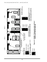
There will be several connectors that must be connected to the wiring at each
PARC-3. The PARC-3 circuit card contains one 7-pin connector for the connection of
cabling from the central control point. The PARC-3 circuit card also contains a 5-pin
connector for the four remote zone alarms if used.
3.3.4
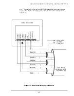
The 3 individually shielded twisted pairs coming from each receiver (03RM)
zone must be connected to one of the four available 6-pin zone connectors on the
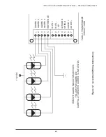
PARC-3 circuit card in accordance with Figure 3-4. Please note that each zone may
consist of multiple 03RM receivers, and in this case 03RM wiring should be in
accordance with Figure 3-5.
3.3.5
Be sure to record the receiver zone numbers and locations in the space
provided. We have purposely provided Figures 3-3 and 3-4 on separate pages of this
manual so you can copy them. Place one with each PARC-3 and keep a copy for your
as-built drawing information.
3.3.6
If the wire colors you have used in your installation are not as shown, please
record your wire colors. Pay attention that the shield connections are not free to touch
metal or ground. Use shrink sleeving to insulate bare wires.
3.3.7
Connect the two pair shielded cables from the central control point (data and
audio) to the 7-pin connector at the end of the PARC-3 board as shown in Figure 3-4.
Once again, observe and record wire colors. Be sure shield connections are firmly
attached and not touching metal or other wiring. If in doubt, use shrink sleeving for
insulation.

