35
INSTALLATION AND OPERATION INSTRUCTIONS — PERSONAL ALARM SYSTEM
4.4
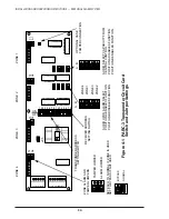
Setting 03RM Receiver Jumpers
4.4.1
The 03RM Receiver contains several jumpers which set the output
configuration of the alarm and tamper signals, as well as the auxiliary alarm contacts.
4.4.2
Set the 03RM alarm relay contacts for normally closed operation by placing JP6
in the “NC” position. See Figure 4-2.
4.4.3
Install JP10 to shunt the 3K ohm resistor in the alarm contact circuit.
See Figure 4-2.
4.4.4
Install JP8 to shunt the 3K ohm resistor in the tamper switch circuit.
See Figure 4-2.
4.4.5
JP9 consists of an eight-pin header with pins labeled from “A” to “H.” These pins
are connected with jumpers in various ways to provide different auxiliary relay and
audio switching functions. Table 4-2 shows the possible jumper configurations. Select
the configuration which suits your system requirements.
4.4.6
Jumper JP7 is used in conjunction with the “sensitivity adjust” potentiometer
to set the range of the receiver. See Section 5.6 for detailed instructions on setting
alarm sensitivity.
4.4.7
Jumpers 1-4 (labeled RUN or SET) and JP5 on the 03RM receiver are for factory
use only and require no changes in the field. Do not alter these jumper settings.


