background image

INSTALLATION AND OPERATION INSTRUCTIONS — PERSONAL ALARM SYSTEM

44

TABLE 5-1

PERSONAL ALARM SYSTEM--TEST REPORT

FACILITY NAME:

ZONE

    AREA NAME

ALARM

LED

AUDIO ACK

COMMENTS

TEST BY:

APPROVED BY:

DATE:

Summary of Contents for PAS-120

Page 1: ...Installation PAS 120 Personal Alarm System Operation Manual T0DA0102 001 Rev A First Edition August 6 2009 ...

Page 2: ...e best of its ability Senstar Corporation is not responsible for any damage or accidents that may occur due to errors or omissions in this manual Senstar Corporation is not liable for any damages or incidental consequences arising from the use of or the inability to use the software and equipment described in this guide Senstar Corporation is not responsible for any damage or accidents that may oc...

Page 3: ...Senstar Corporation website www senstar com email info senstar com INSTALLATION AND OPERATION INSTRUCTIONS PAS 120 PERSONAL ALARM SYSTEM August 2009 Rev A ...

Page 4: ... or materials This warranty shall not apply to any products which have been installed repaired or altered by other than personnel certified by the Company or to products which have been subject to physical or electrical abuse misuse or improper storage or to products which have not been used or maintained in compliance with any applicable recommendations of the Company This warranty does not apply...

Page 5: ...ver 03RM Installation 18 3 3 Receiver Communicator PARC 3 Installation 21 3 4 Central Control Installation 22 4 0 INITIAL SET UP AND ADJUSTMENT 29 4 1 General 29 4 2 Setting Transponder and Receiver Addresses 29 4 3 Setting PARC 3 Jumpers 32 4 4 Setting 03RM Receiver Jumpers 35 4 5 Initial Setup of Central Control Equipment 38 5 0 SYSTEM STARTUP AND TESTING 39 5 1 General 39 5 2 Power Requirements...

Page 6: ... Tamper Switch Activation 20 Figure 3 3 03RM Receiver Wiring Connections 23 Figure 3 4 PAS 120 03RM to PARC 3 Interconnect Wiring 24 Figure 3 5 PAS 120 03RM to PARC 3 Interconnect Wiring Multiple 03RM S 25 Figure 3 6 PAS 120 03RM IV to PARC 3 IV Interconnect Wiring 26 Figure 3 7 Local Alarm Wiring Connections 27 Figure 3 8 LAP Wiring Connections 28 Figure 4 1 PARC 3 Transponder Circuit Card Switch...

Page 7: ...em Unique proprietary two frequency ultrasonic transmission significantly reduces nuisance alarms present in earlier competitive systems High power portable transmitter enables reliable coverage with fewer receivers than with previous ultrasonic alarm systems Ease of installation provided with simple wiring and plug in connections Portable Transmitter PAT S Rugged case molded from Lexan plastic Un...

Page 8: ...D alarm lamp Built in microphone for audio verification Optional video output for visual verification 03RM IV Built in self test circuitry Receiver Communicator PARC 3 Proven CenDe multiplex communications minimizes wiring requirements Four PAS Receiver zone inputs Auxiliary outputs for local alarms Audio switcher for listen in on any zone Optional video switcher available PARC 3 IV ...

Page 9: ...enstar employs a unique method of using two ultrasonic frequencies in a preset modulation pattern to overcome these nuisance alarm problems With this concept a signal must not only consist of the two frequencies but must also be coded in the proper pattern The combination of these new conditions makes a nuisance alarm far less likely than with any similar personal alarm system 2 1 4 Senstar has su...

Page 10: ...e 2 1 PAS 120 Transmitter 2 2 5 Battery power for the PAT S is provided by a 9V Lithium battery capable of providing power for up to 100 hours of continuous transmitting time or several years in normal operation The PAT C is powered by A 9V Lithium battery pack which provides an operating life of about 1 year Battery voltage is constantly monitored and a low battery indication is given when batter...

Page 11: ...unique frequency and modulation pattern generated by the PAS transmitter If the alarm signal is present the red LED on the front panel lights and a relay contact communi cates the alarm condition to the PARC 3 Receiver Communicator The microphone receives the sounds in the immediate area These signals are also amplified and sent to to the PARC 3 for processing An optional video output provides rea...

Page 12: ...r supply 2 4 Receiver Communicator PARC 3 2 4 1 The PARC 3 is the unit that receives alarm and audio signals from the 03RM units processes those signals and sends the alarms and audio to the central control point Each PARC 3 contains the circuitry that interfaces to the 03RM units and the multiplex transponder circuitry that communicates the alarm information to the central control point using the...

Page 13: ...s for use as local alarm activation one for each receiver zone This output can be used to signal a local zone light or audible alarm Only limited current is available 2 4 7 Power for each PARC 3 is normally provided from a local power supply such as the UPS PFI The local power supply powers the PARC 3 and all connected 03RM receivers 2 4 8 Audio features are selected by configuring jumpers on the ...

Page 14: ...UDIO SWITCH AUDIO SWITCH REGU LATOR FILTER AUDIO SELECT JUMPERS 12 VDC TEST OUTPUT LOCAL ZONE LAMP DRIVER ALARM SELECT JUMPERS TAMPER SELECT JUMPERS TO ACTIVATE LOCAL ALARMS SIGNAL LINES TO CENTRAL CONTROL POINT TO INDIVID UAL PARC 3 ZONE PORT POWER FOR PARC 3 POWERFOR 03RM S LOCAL POWER SUPPLY Figure 2 3 PARC 3 Transponder Circuit Card ...

Page 15: ... one for each zone allow the operator to acknowledge each alarm and silence the audio tone A subsequent push of the button resets the zone Secure zones are indicated by a green LED Acknowledging and resetting alarms on the LAP does not affect the central control alarm annunciation and command functions Figure 2 4 illustrates the faceplate of the LAP 2 5 3 When used in a PAS 120 system the LAP draw...

Page 16: ... zones and where the control and annunciation equipment will be integrated into a control console The MX 2000 is also suited for operation with remote graphic annunciators and other remote alarm reporting equipment 2 6 4 The MX 2000 contains the same type of transponding equipment as the PARC 3 units Each MX 2000 data line can accommodate up to 10 PARC 3 units each or 40 alarm zones Three data lin...

Page 17: ...ntion should be paid to the installation of the wiring system because many problems occurring after installation are traced to the incorrect type or installation of wiring 3 1 5 All wiring must be installed in accordance with the latest edition of the National Electrical Code Wiring should be installed in conduit whenever possible The personal alarm system wiring should be separated from the wirin...

Page 18: ... Belden Catalog No 8777 West Penn Catalog No 431 or equivalent 3 1 9 2 Wiring from PARC 3 transponder to central control 2 individually shielded twisted pairs 18 AWG stranded conductors in overall jacket Belden Catalog No 9368 West Penn Catalog No 440 or equivalent See Note NOTE If special cable conditions exist such as high moisture conditions or multiple data cables in a single conduit consult t...

Page 19: ...es 1 81 03RM IV Figure 3 1 03RM Receiver Mounting Dimensions 3 2 2 Tamper switch activation is by way of two self adhesive permanent magnets supplied with the receiver Position these magnets on the inside surfaces of the box using the template provided See Figure 3 2 The receiver electronics are mounted to a combination trim and mounting plate SS 040 which mates to standard two gang boxes ...

Page 20: ...tion 3 2 3 Wiring connections are via a 10 position plug in connector Attach the connector to the wiring before plugging connector into circuit board The wiring must be attached to the connector in accordance with Figure 3 3 Figure 3 3 shows wire colors for the type of wire normally used If the colors of your cable are different change the wire colors listed on Figure 3 3 and retain as your as bui...

Page 21: ...one alarms if used 3 3 4 The 3 individually shielded twisted pairs coming from each receiver 03RM zone must be connected to one of the four available 6 pin zone connectors on the PARC 3 circuit card in accordance with Figure 3 4 Please note that each zone may consist of multiple 03RM receivers and in this case 03RM wiring should be in accordance with Figure 3 5 3 3 5 Be sure to record the receiver...

Page 22: ...s a nearby PAT is transmitting 3 3 10 Configure the audio jumpers for each zone to provide the desired audio features including 1 audio on alarm 2 on alarm and on command 3 on command only and 4 disabled 3 3 11 Following completion of all connections to the PARC 3 take a moment to verify that all connections are secure and proper Before installing cover verify that the PARC 3 transponder addresses...

Page 23: ...that there are no grounds or shorts in the wiring system before the Monitor Control equipment is connected TAMPER TAMPER POWER POWER ALARM 1 ALARM 1 TEST AUDIO OUT ALARM 2 AUX ALARM 2 AUX 03RM RECEIVER AUXILIARY ALARM CONTACT RED BLACK BLACK GREEN WHITE BLACK CUT BACK AND INSULATE ALL SHIELDS Figure 3 3 03RM Receiver Wiring Connections ...

Page 24: ... ALARM POWER AUDIO GROUND TEST TAMPER ALARM POWER PARC 3 ZONE 4 ZONE 3 ZONE 2 ZONE 1 DATA DATA POWER GND SHLD AUD AUD TO MX 2000 03RM RECEIVER TAMPER TAMPER POWER GROUND ALARM ALARM TEST AUDIO OUT ALARM 2 AUX ALARM 2 AUX ALARM 3 ALARM 3 WHITE BLACK GREEN BLACK RED BLACK SHIELDS ARE NOT CONNECTED AT RECEIVER TO UPS PFI Figure 3 4 03RM Receiver to PARC 3 to MX 2000 ...

Page 25: ...ATA DATA POWER GND SHLD AUD AUD TO MX 2000 03RM RECEIVER TAMPER TAMPER POWER GROUND ALARM ALARM TEST AUDIO OUT ALARM 2 AUX ALARM 2 AUX ALARM 3 ALARM 3 03RM RECEIVER TAMPER TAMPER POWER GROUND ALARM ALARM TEST AUDIO OUT ALARM 2 AUX ALARM 2 AUX ALARM 3 ALARM 3 03RM RECEIVER TAMPER TAMPER POWER GROUND ALARM ALARM TEST AUDIO OUT ALARM 2 AUX ALARM 2 AUX ALARM 3 ALARM 3 TO UPS PFI Figure 3 5 03RM Receiv...

Page 26: ...PER TEST GROUND AUDIO POWER ALARM TAMPER TEST GROUND AUDIO POWER ALARM TAMPER TEST GROUND AUDIO ZONE 2 ZONE 3 ZONE 4 AUD AUD SHLD GND POWER DATA DATA TAMPER TAMPER POWER GROUND ALARM ALARM TEST AUDIO OUT ALARM 2 AUX ALARM 2 AUX 03RM IV TO LOCAL POWER SUPPLY AUX VIDEO OUT VIDEO BUS ZONE 2 ZONE 3 ZONE 4 ZONE 1 BNC PARC 3 IV VIDEO SWITCH AUX VIDEO OUT RG 59 U CENTER SHIELD TO OPTIONAL VIDEO SWITCHER ...

Page 27: ... 4 5 1 2 3 4 5 6 7 ALARM 1 ALARM 2 ALARM 3 ALARM 4 REFERENCE DATA DATA PP GROUND SHIELD AUDIO AUDIO PARC 3 TRANSPONDER CIRCUIT CARD 12 VDC REMOTE ALARM INDICATION DEVICES FOLLOW PAR ALARM LED CAREFULLY OBSERVE CURRENT LIMITATIONS Figure 3 7 Local Alarm Wiring Connections ...

Page 28: ...SYSTEM 28 1 2 3 4 5 1 2 3 4 5 6 7 ALARM 1 ALARM 2 ALARM 3 ALARM 4 REF DATA DATA PP GROUND SHIELD AUDIO AUDIO JP20 19 18 17 4 A L M 3 A L M 2 A L M 1 A L M G N D 1 2 LAP INSTALL JUMPERS JP 20 THRU JP 17 TO POWER SUPPLY PARC 3 Figure 3 8 PARC 3 to LAP Wiring ...

Page 29: ...ess and one transponder address for each PARC 3 on the system For example a PARC 3 is capable of four zones so a 40 zone central unit MX 2040 can address 10 PARC 3 units and contains one set of receive and transmit addresses for each The MX 2040 is microprocessor controlled and all the receiver and transponder addresses are contained in software There are no switches inside the MX 2000 similar to ...

Page 30: ...imizes the need to rearrange the zone configuration with the MX 2000 but is not required 4 2 7 Table 4 1 shows the settings for the 10 PARC 3 transponders the zones associated with each PARC 3 transponder and the settings for the PARC 3 switches that are associated with those zones Most systems can be set up using this standard set of PARC 3 switch settings These settings are repeated on loops two...

Page 31: ...8 9 12 13 16 17 20 21 24 25 28 29 32 33 36 37 40 ON POSITION IS THE TOP OF EACH SWITCH BLACK SQUARE INDICATES SW POSITION 03RM ZONES VPP VOLTAGE READINGS PROJECT NAME ON OFF ON OFF ON OFF ON OFF ON OFF ON OFF ON OFF ON OFF ON OFF ON OFF 1 2 3 4 5 6 7 8 1 2 3 4 5 6 7 8 1 2 3 4 5 6 7 8 1 2 3 4 5 6 7 8 1 2 3 4 5 6 7 8 1 2 3 4 5 6 7 8 1 2 3 4 5 6 7 8 1 2 3 4 5 6 7 8 1 2 3 4 5 6 7 8 1 2 3 4 5 6 7 8 1 2...

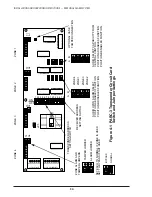
Page 32: ...eceiver 03RM is not connected 4 3 2 3 One jumper is provided for connection of an optional PARC 3 case tamper switch If the optional tamper switch is provided the case tamper jumper is removed and the leads from the tamper switch are connected in place of the jumper 4 3 2 4 Two sets of four jumpers control the selection of the audio monitoring for each zone One set of jumpers determines whether au...

Page 33: ...t or across 2 3 to disable local annunciation 4 3 2 8 Figure 4 1 is a diagram of the PARC 3 transponder circuit board showing the locations of each jumper Set the jumpers as required for your application Copy Figure 4 1 for each PARC 3 in your system record the location of each jumper and retain with your as built information 4 3 3 Other jumpers on the PARC 3 board are for factory use and require ...

Page 34: ...L IF ZONE IS USED SET TO BYPASS IF NOT USED AUDIO UPON ALARM SELECT POSITION A ENABLES FUNCTION POSITION B DISABLES FUNCTION AUDIO SELECT CAPABILITY FROM CENTRAL CONTROL POSITION A DISABLES FUNCTION POSITION B ENABLES FUNCTION Figure 4 1 PARC 3 Transponder Circuit Card Switch and Jumper Settings JP5 A B A B ON OFF T1 A1 T2 A2 T3 A3 T4 A4 RECEIVER ADDRESS SETTING SWITCH TRANSPONDER ADDRESS SETTING ...

Page 35: ...resistor in the tamper switch circuit See Figure 4 2 4 4 5 JP9 consists of an eight pin header with pins labeled from A to H These pins are connected with jumpers in various ways to provide different auxiliary relay and audio switching functions Table 4 2 shows the possible jumper configurations Select the configuration which suits your system requirements 4 4 6 Jumper JP7 is used in conjunction w...

Page 36: ...9 JP 8 TMPR POWER ALM 1 OUT T S T AUD OUT ALM 2 AUX ALM 3 OUT HI SENS JP 7 3K ALM NO NC 3K TMPR R S S R U E E U N T T N Senstar Corp 06 200900 REV PAS RECEIVER MADE IN USA INSTALL JUMPERS INSTALL JUMPER TO SHUNT 3K RESISTOR SEE TABLE 4 2 FOR JUMPER INFORMATION Figure 4 2 Rear View 03RM Receiver Component Locations ...

Page 37: ...mp A B Jump A B C D H G Jump A B C D G F Jump A H B C Function Definitions Standard Audio Auxiliary Relay Audio Switching Audio signal is always available at audio terminal of 03RM receiver Auxiliary alarm relay contacts actuate with alarm relay configurable for normally open N O or normally closed N C operation When PAS zones consist of multiple receivers the auxiliary contact can be used to swit...

Page 38: ...up procedure for the central control equipment must be followed in conjunction with the initial setup of the PAS 120 4 5 2 If you are installing the MX 2000 proceed with the procedures in the Initial Setup and Adjustment section of the MX 2000 Installation and Operation Instructions 4 5 3 If you are installing the Data Collection Unit proceed with the procedures of Section 6 0 System Setup of the ...

Page 39: ...ATERS ON 03RM WPH MODELS SHOULD NOT BE POWERED FROM THE PARC 3 RUN A SEPARATE 12 VDC POWER CIRCUIT FOR THE HEATERS 5 2 2 The PARC 3 s are powered individually or in groups depending on the number of 03RM s connected to each PARC 3 and the relative location of the PARC 3 s in your system Regardless of the method selected always use a dedicated DC supply not shared with any other system of from 12 t...

Page 40: ... is less than 1 2 Amp rating c Battery capacity is sufficient to meet minimum back up requirement for total combined load The following chart is provided to assist you in determining the total current load of each PARC 3 PARC 3 alone 035 Amps No __________ 03RM and 03RM WP X 040 _________ Amps No __________ 03RM IV X 120 _________ Amps Total current load per PARC 3 ___________ Amps The AC voltage ...

Page 41: ... adjustments at the PARC 3 9 ADJ control unless instructed by the factory 5 3 Initial Testing 5 3 1 At this time you should have set and checked the following items at each of the PARC 3 units in the field Transponder Receiver addresses are correct All jumpers have been correctly set All voltages are within tolerance 5 3 2 All of the connections and initial adjustments of field devices PARC 3 and ...

Page 42: ...e if audio signals are being picked up Record areas where audio is not received or appears to be of poor quality Refer to the troubleshooting procedure NOTE Remember if the Receiver Audio Switching mode is selected audio will only be available from a particular 03RM receiver while an alarm condition exists at that Receiver 5 5 Final Tests 5 5 1 This final test procedure is a guideline for system a...

Page 43: ...d level When making the audio tests remember that the system is designed to pick up the sounds of disturbances Depending on the room acoustics it may be difficult to understand what is said Check for hum or other improper sounds 5 5 8 If the receiver sensitivity or audio level is questionable refer to the adjustment sections Retest after any adjustments 5 5 9 The final test procedure should be run...

Page 44: ...INSTALLATION AND OPERATION INSTRUCTIONS PERSONAL ALARM SYSTEM 44 TABLE 5 1 PERSONAL ALARM SYSTEM TEST REPORT FACILITY NAME ZONE AREA NAME ALARM LED AUDIO ACK COMMENTS TEST BY APPROVED BY DATE ...

Page 45: ...t zones when zones are small Make fine sensitivity adjustments using the sensitivity adjustment potentiometer 5 6 4 Using a known good transmitter with fresh battery periodically set off alarms at the receiver location requiring adjustment Slowly change sensitivity by turning the control in the proper direction Do not turn the adjustment potentiometer more than 10 degrees between tests DO NOT OVER...

Page 46: ...Remove receiver from box to make adjustment Clockwise adjustment increases level Counterclockwise decreases level HI SENS JP7 AUDIO VOL SENS ADJ HIGH SENSITIVITY JUMPER JP7 AUDIO VOLUME POT SENSITIVITY ADJUST POT STAINLESS FACE MOUNTING PLATE Figure 5 1 03RM Receiver Board ...

Page 47: ... known good personal alarm transmitter 6 1 3 Once per quarter each field device should be tested using a known good transmitter Inspect each device for physical damage LED alarm and audio quality Record tests on a copy of Table 5 1 6 2 Cleaning Adjustment 6 2 1 Special cleaning and adjustments are not required if the system adequately passes the system testing 6 3 Special Requirements 6 3 1 The fa...

Page 48: ...INSTALLATION AND OPERATION INSTRUCTIONS PERSONAL ALARM SYSTEM 48 This page intentionally left blank ...

Page 49: ...er or lightning damage 7 1 4 Factory customer assistance is available to help you find and correct system errors It is important that you fill out the tables contained in this manual during your installation so they can be Faxed to the factory at 613 839 5830 if you are in need of assistance 7 2 Problem Identification and Resolution 7 2 1 Table 7 1 is provided to help you find and resolve system d...

Page 50: ...nown good components or by using spare components reserved for maintenance actions For example a suspected defective 03RM can be isolated by swapping its wiring with an adjacent 03RM at the PARC 3 If the problem moves to the other zone the problem is the 03RM or the wiring If the problem stays with the bad zone the problem is probably in the zone PARC 3 7 3 3 Return components thought to be defect...

Page 51: ... ther system tests below The following tests are applicable after self test has been run and has failed in one or more zones Self test failure in one zone Defective PARC 3 Verify whether just one or all four zones All four zones failed is probably a PARC 3 failure Defective receiver At the PARC 3 swap the zone receiver connectors coming from the PARs If the def ective zone moves replace the PAR If...

Page 52: ...ot report defect Plugged or covered receiver Inspect receiver for physical damage Verify that the faceplate has not been plugged Inspect ultrasonic and microphone elements for damage Defective ultrasonic element or microphone Replace receiver PAR with known good unit and retest Self test failure on all four zones of PARC 3 Defective cables Check Vpp voltage at PARC 3 Vpp must be within tolerance I...

Page 53: ...onnectors at PARC 3 card If defect moves re place receiver If defect does not move replace PARC 3 and retest Audio not present upon alarm or Audio not capable of selection at central Improper jumper setting Check audio jumpers on PARC 3 See Figure 4 1 Check JP9 on PAR See Table 4 2 Defective receiver Replace receiver and retest Defective PARC 3 Replace and retest Hum in audio signal Cable shield i...

Page 54: ...INSTALLATION AND OPERATION INSTRUCTIONS PERSONAL ALARM SYSTEM 54 APPENDIX ...

Page 55: ...nal is transmitted in all directions You DO NOT have to point your PAT at the receiver s A PAT S Model A 1 SENDING AN ALARM A 1 1 ACTIVATE the emergency signal by depressing the red button located on top of your PAT S Once pressed the red button will latch down even though you remove your hand Your PAT S will constantly send the emergency signal until the red button is reset RESET the alarm by pre...

Page 56: ...ople If you wish to move the belt clip to the oppo site side proceed as follows A 3 2 1 Turn your PAT S so the narrow side is facing you A 3 2 2 Insert a blunt object in the small gaps of the decorative wedge and gently lift the wedge away from the PAT S Remove the wedge from the PAT S A 3 2 3 Remove the belt clip by gently pressing the keepers and sliding the belt clip from the PAT S Insert the b...

Page 57: ... DOWN alarm will automatically transmit an emergency signal whenever you are in a prone position The MAN DOWN feature may be enabled or disabled via an on off switch A 6 2 TURN ON the MAN DOWN feature by inserting a blunt object such as a ball point pen into the small hole located on the side of the unit just below the red alarm button and press the switch into the up position toward the red butto...

Page 58: ...l constantly send the emergency signal until it is reset RESET the PAT C by pressing the gray button again to release it from its locked position The button will rise and your PAT C is now reset B 1 2 BY KEEPER SWITCH Your PAT C can also be activated by pulling the keeper switch located at its base This allows the unit to be worn on a breakaway type necklace keeper chain etc The unit is reset by p...

Page 59: ...ining a short audible beep will be heard every 2 minutes This warning tone will repeat until new batteries are installed If the warning tone ceases the battery power has been completely depleted and your PAT will be inoperative B 3 INSTALLING NEW BATTERIES B 3 1 Turn the PAT C so the back side with clip is facing you B 3 2 Remove both security screws above the clip with the small security screwdri...

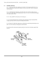
Page 60: ...RATION INSTRUCTIONS PERSONAL ALARM SYSTEM Remove both security screws Separate case here Security screwdriver INSTALL BATTERY PACK OBSERVE POLARITY 60 B 3 4 Remove the old battery pack and install a new one Observe polarity ...

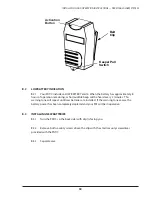
Page 61: ... B 4 1 The PAT C can be clipped directly on your belt a pocket lapel or attached to clothing or break away necklace with the keeper ring Wear or carry the unit outside of clothing Do not cover your PAT C with heavy jacket robe or lab coat The activation button is top center to accommodate either right or left handed people B 5 REMOVE AND DISCARD THE PLASTIC TAB PROTECTING THE BATTERIES DURING SHIP...

Reviews: